Dyness Battery Alarm and SOC Light Meanings Guide
Updated 6 September 2026 · By SolarNevs Research Desk, Dealer surveys + verified sources · 4 sources · Method ↗
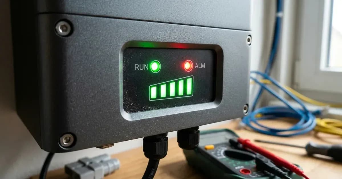
Key Takeaways
- Solid red ALM indicates active BMS protection lockout (auto-clears once the trigger condition is released); flashing red ALM indicates an early operational warning with continued operation.
- RUN LED flashes during standby and charging; RUN remains solid green during discharging.
- Inverter charge voltage setpoints (53.5 V or 54 V for 48V B4850, and 56.5 V or 57 V for 51.2 V DL5.0C / BX51100) resolve failing to reach 100% SOC under the 15–30°C optimal ambient band (standard charging window is 0°C to 55°C; BMS halts charging above +65°C).
- BMS protection automatically stops charging above +65°C (datasheet operating spec is 0°C to 55°C; optimal ambient 15–30°C) or if charge current exceeds 90A on DL5.0C or 45A on B4850.
- All LEDs flashing simultaneously on the master module indicates inter-battery (master↔slave) communication loss.
How do I interpret the indicator lights on my Dyness battery?
Dyness LiFePO4 residential batteries (including the B4850, BX51100, and DL5.0C) use front panel LED indicators and an audible buzzer to report live operational status, State of Charge (SOC), early warnings, and critical Battery Management System (BMS) protection events. The alarm surfaces as an LED pattern plus the buzzer rather than as a numeric code on a screen, so reading these LED color patterns and flashing rhythms is the primary method for diagnosing system performance.
The first step in diagnosing your Dyness battery is determining whether the red ALM light is flashing (warning) or solid (protection shutdown), and checking the green RUN and SOC bar patterns.
Comprehensive Dyness LED Status and Alarm Table
The table below compiles official LED behavior from the Dyness B4850 and DL5.0C user manuals:
Power Switch | RUN (Green) | ALM (Red) | SOC Bar LEDs | Operating State | Meaning & Required Action |
|---|---|---|---|---|---|
OFF | OFF | OFF | All OFF | Power Off | System completely shut down. BMS unpowered. |
ON | Flashing Green | OFF | Level Bar (Top Flashes) | Standby / Charging | Normal standby or charging. Solid LEDs show capacity; flashing LED shows active segment. |
ON | Solid Green | OFF | Solid Bar at Current Level | Discharging | Normal discharging. Solid LEDs indicate remaining capacity (4 LEDs on B4850, 5 on DL5.0C). |
ON | Flashing or Solid | Flashing Red | Normal Display | Alarm / Warning | Parameter approaching limit (high temp, over-current). Battery continues operating. |
ON | — | Solid Red | — | Protection Active | BMS protection has stopped charge or discharge due to over-current, undervoltage (total-voltage or cell), or a temperature fault. Auto-clears once the trigger condition is released. |
ON | — | Red + Buzzer | — | Undervoltage Alarm | Total-voltage or cell undervoltage during discharge. Start charging immediately. |
ON | All LEDs Flashing | All LEDs Flashing | All Flashing | Inter-Battery Fault | Master↔slave communication lost or abnormal. Check the RJ45 link cables between modules. |
B4850 features 4 SOC LEDs (25% steps); DL5.0C features 5 SOC LEDs (20% steps). A dash (—) means the manuals do not specify that LED's state for the row.
Understanding Protection Thresholds and BMS Trigger Values
Dyness battery management systems enforce strict hardware safety bounds to protect LiFePO4 cells from permanent damage:
- Charge Over-Current Protection:
- B4850 (48V module, 50A max): If charge current exceeds 45A, the BMS throttles current to ≤3A and retries after a 10 s delay.
- DL5.0C (per its manual): If charge current exceeds 90A, current is limited to ≤3A on a 10 s cycle. The BX51100 datasheet quotes different limits — recommended 0.5C (50A), 75A maximum continuous charge, 100A peak for 15 seconds — so check the document for your exact model.
- Discharge Over-Current Protection:
- B4850: If discharge current exceeds 55A, the buzzer sounds and discharge stops, automatically recovering after 1 minute (60 seconds).
- DL5.0C (per its manual): If discharge current exceeds 110A, discharge halts after 15 seconds, recovering after 60 seconds (or immediately once charging current appears). The BX51100 datasheet lists 75A maximum continuous discharge with a 100A peak for 15 seconds.
- Temperature Protection Windows:
- Charging is automatically halted if internal cell temperatures exceed +65°C or drop below 0°C (standard operating spec is 0°C to 55°C). Discharging is halted outside −20°C to +65°C (datasheet operating spec is −20°C to 55°C).
- BMS Limits on CAN Bus (as documented in the Dyness + Victron setup manual):
- The BMS dynamically reports Charge Voltage Limit (CVL) as 53.5 V for 48V models and 56.5 V for 51.2 V models. When State of Charge reaches 100%, Charge Current Limit (CCL) drops to 0A. When SOC falls to 15%, Discharge Current Limit (DCL) drops to 0A to prevent deep discharge.
Step by step Diagnostic and Reset Procedure
When an alarm or protection shutdown occurs on your Dyness battery:
- Identify the Trigger Condition: Dyness publishes no public numeric fault-code table — alarms are reported through the LEDs and buzzer, plus any battery related code shown on the inverter side. Check the inverter LCD for a battery related fault message, and measure module terminal voltage using a DC voltmeter.
- Address Underlying Electrical Causes:
- If total pack voltage is below 35 V, the BMS cannot power on due to deep discharge; contact an installer for low-voltage recovery charging.
- If the battery fails to reach 100% SOC, raise the inverter's charge voltage setting to 53.5 V or 54 V for B4850 (48V) or 56.5 V or 57 V for BX51100/DL5.0C (51.2 V) — these setpoints apply under the 15–30°C optimal ambient range (charging halts above +65°C).
- If the battery room runs well above the recommended 15–30°C optimal ambient range, improve ventilation so the cells can cool back toward it.
- Inspect Inter-Battery Link Cabling:
- If all LEDs flash simultaneously, check that the RJ45 link cables between the master and slave modules are correctly seated. Verify that all slave DIP switches remain set to 0000.
- Execute System Restart / Wakeup:
- If the battery entered dormant standby after 72 hours of inactivity with no load, charge, or comms, press and hold the SW (Start) button for 3 seconds.
- For a full system reset: switch off the inverter first, isolate the battery DC breaker and power switch (using insulated tools to avoid short circuits discharging hundreds of amperes), switch the battery back on, press the SW button for 3 seconds, and power on the inverter.
If communication faults persist following reset, refer to our detailed walkthrough on Dyness battery communication fault fixes for CAN and RS485.
Safe Handling and Environmental Rules for LiFePO4
Observe these essential safety guidelines when maintaining Dyness battery systems:
- Buzzer Safety Function: Do not permanently silence the internal warning buzzer to "fix" an alarm — it is your audible warning of an over-current or undervoltage condition. The manuals note it can be switched off in Dyness service software, but it ships on by default for a reason.
- Operating Temperature Reality in Pakistan: Dyness specifies a working range of −20°C to +55°C with an optimal ambient of 15–30°C and storage from −10°C to +35°C — ventilate battery rooms so summer temperatures stay as close to that optimal band as possible. Understand why LFP chemistry excels in local climates in our guide on why LiFePO4 beats other lithium chemistries for Pakistani heat and review BMS functions and battery protection.
- Pack Operating Voltage & Scaling: Operating voltage windows span 44.8–57.6 V for the BX51100 (51.2 V nominal, supporting up to 30 units in parallel) and 42–54 V for the B4850 (48V nominal, supporting up to 40 modules in parallel). Working temperature is −20 to +55°C (charging 0–55°C, discharging −20–55°C; optimal ambient 15–30°C). Ensure installations remain indoor only (IP20) avoiding direct sun, conductive dust, corrosive gas, and flammables, and confirm SELV compliance with >42 V verified at breaker terminals before closing breaker.
- Weight and Mounting: DL5.0C weighs 54 kg while B4850 weighs approximately 22 kg — require two-person lifting and solid-wall anchoring.
- Warranty Terms: Multiple Pakistani dealers claiming authorized distributor status (including AMS Security Vision and W11Stop) advertise 10-year manufacturer warranty coverage (with AMS adding a 2-year local replacement warranty) — Dyness has no single exclusive distributor in Pakistan, so treat warranty terms as distributor-reported.
For general charging faults, consult our parent diagnostic guide on solar battery not charging and our guide on lithium battery inverter compatibility errors.
When to call a technician instead
Contact a certified solar technician or authorized Dyness service center under the following conditions:
- The red ALM light remains permanently solid after multiple cold restarts with normal terminal voltages.
- Pack terminal voltage measures below 35 V and the module fails to wake via the SW button.
- A spark occurs at the battery power cable connections with a red ALM light — the manuals attribute this to a short circuit in the power connection: isolate DC power first (using insulated tools to avoid short circuits discharging hundreds of amperes) and have the short located before restoring power.
For professional escalation standards, consult our guide on when to call a solar technician.
Figures as of August 2026.
Still showing the fault? Book a technician
If the steps above did not clear it, tell us the inverter or battery and the exact code. We pass it to a technician who covers your city; visit charges are quoted before they come.
How this pays for the site: the technician or verifier pays SolarNevs a fixed introduction fee. Nobody pays to be recommended, and you are free to use our free guides instead.
Frequently asked questions
What does a solid red ALM light on a Dyness battery mean?
A solid red ALM light indicates an active BMS protection state. The battery has temporarily disconnected charge or discharge circuits due to over-current, extreme temperature, or undervoltage (total-voltage or cell), and auto-clears once the trigger condition is released.
What does a flashing red ALM light mean on a Dyness battery?
A flashing red ALM light indicates an operational alarm or warning condition (such as over-current, high temperature, or undervoltage). The battery continues to operate while signaling the warning.
What does it mean when all LEDs flash together on a Dyness battery?
When all green SOC LEDs and the RUN light flash simultaneously on the master battery, inter-battery (master↔slave) communication is lost. Check the RJ45 link cables between the modules and verify slave DIP switches remain set to 0000.
Why is my Dyness battery not charging up to 100% SOC?
Dyness manuals state that failing to reach 100% SOC is caused by inverter charge voltages set too low. These setpoints apply under the 15–30°C optimal ambient band (standard charging window is 0°C to 55°C; BMS halts charging above +65°C). For 48V B4850 models, set charge voltage to 53.5 V or 54 V; for 51.2 V DL5.0C/BX51100 models, set charge voltage to 56.5 V or 57 V.
Why did my Dyness battery shut down after several days of storage?
Dyness batteries feature an automatic self-shutdown safety timer. If left without load, charging, or communication for 72 hours, the BMS enters dormant standby to conserve energy. Press the SW button for 3 seconds to restart.
References
- Dyness B4850 User Manual PDF — accessed 23 August 2026
- Dyness DL5.0C User Manual PDF — accessed 23 August 2026
- Dyness BX51100 Technical Datasheet — accessed 23 August 2026
- Dyness and Victron Inverter Setup Manual — accessed 23 August 2026
Related guides
More from inverter errors & fixes.