Dyness Battery Communication Fault Fix: CAN and RS485 Inverter Setup
Updated 6 September 2026 · By SolarNevs Research Desk, Dealer surveys + verified sources · 6 sources · Method ↗
Key Takeaways
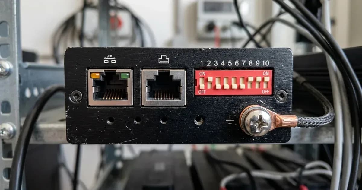
- Dyness communication faults stem from mismatched master DIP switches, wrong inverter protocol profiles, or miswired RJ45 network cables.
- Configure Master battery DIP switches to 0010 (#3 ON) for CAN communication across Solis, Deye, and Victron inverters.
- Slave batteries in parallel strings must have all DIP switches set to 0000; never change DIP switches on slave units.
- Dyness batteries enter dormant self-shutdown after 72 hours of inactivity; hold the SW button for 3 seconds to re-awaken the BMS.
- Inverter charge voltage setpoints (53.5 V or 54 V for 48 V B4850, and 56.5 V or 57 V for 51.2 V DL5.0C / BX51100) are referenced to 25°C under the 15–30°C optimal ambient band (standard charging window is 0°C to 55°C; BMS halts charging above +65°C).
Why is my solar inverter showing a Dyness communication fault?
A solar inverter connected to Dyness LiFePO4 battery modules (including the B4850, BX51100, and DL5.0C) shows a communication error when digital CAN bus or RS485 data packets are not received by the inverter's control board. Because Dyness lithium batteries manage safety via closed-loop BMS communication, a communication failure prevents the inverter from reading dynamic charge current limits, pack temperature, and precise state of charge.
Dyness official engineering documentation identifies five core causes: incorrect master DIP switch configuration, the wrong battery type selected on the inverter, the wrong communication cable, a cable plugged into the wrong comm port on either the battery or the inverter, or battery firmware too old for the inverter.
Step-by-step diagnosis and communication fault resolution
Follow these sequential diagnostic steps using official Dyness manual guidelines:
- Verify Master Battery DIP Switch Configuration:
- Action: Inspect the DIP switch bank on the master battery (the module connected to the inverter).
- CAN Protocols (Solis, Deye, GoodWe, Victron): Set DIP switches to 0010 (#3 ON).
- Voltronic Axpert (King/VM III/MAX) & Growatt SPH: Set DIP switches to switch 2 ON (#2 ON).
- Growatt SPF Series (RS485 Mode): Set DIP switches to 0110 (#2+#3 ON).
- Slave Batteries: All slave modules in a parallel bank must have their DIP switches set to 0000.
- Verify Model-Specific RJ45 Pinouts:
- Dyness B4850 (CAN/485 Port): PIN1 485A, PIN3 485B, PIN4 CANH, PIN5 CANL. RJ45 pinouts differ by model — never print or apply one model's pinout as the general Dyness pinout; always verify your specific model.
- Dyness DL5.0C (COM Port): PIN1 485B, PIN2 485A, PIN4 EXT-CANH, PIN5 EXT-CANL (PIN7/8 internal CAN).
- Growatt SPF Wiring Tip (community-reported): Installers on the DIY solar and Powerforum boards report that the RS485 pin positions in a straight cable do not match Growatt's port, and that moving the Dyness B4850 onto CAN instead — master DIP 0010, PIN4 CANH and PIN5 CANL, Program 05 set to "LI", Program 36 set to L52 — is what brings the link up. This is community-reported, not an official Dyness or Growatt instruction.
- Inspect Communication Port Connections:
- Action: Ensure the inverter communication cable runs from the IN port (the master CAN IN port) on the Master battery to the matching comm port on the inverter. Dyness manuals list "cable plugged into wrong comm port" as one of the five named causes of a communication fault, so confirm both ends against your model's manual rather than by eye.
- Inter-Module Cascading: Link the master to the first slave, then each slave to the next, so every module sits on one continuous chain. Port labelling differs between Dyness models, so follow the cascade diagram in your own model's manual instead of assuming another model's layout.
- Confirm Inverter Protocol Selection:
- Solis Hybrid Inverters: Advanced Settings (password 0010) → Storage Energy Set → Battery Select → select "Dyness LV". Run master CAN IN to inverter on a pin-to-pin RJ45 cable with master DIP 0010, slaves 0000.
- Deye Hybrid Inverters (installer-documented): Battery Setting → Batt Mode "Lithium" → Batt Set3 → select Lithium Mode 00 (CAN), per installer-published setup guides. Battery IN port into Deye CAN port with master DIP 0010.
- Growatt SPF Series: Program 05 = "LI". Program 36 = "L01" is the documented RS485 setting; "L52" for CAN is the community-reported workaround described above.
- Voltronic Axpert Series: Set Program 05 to "LIb" (or "PYL" on some firmware) — this Program 05 naming is community-reported. Master DIP switch 2 ON (#2 ON).
- Voltage Mode Calibration Notice: If running in voltage mode without BMS communications, fix values differ by family: B4850 (48 V) requires 53.5 V or 54 V, while the DL5.0C / 51.2 V family requires 56.5 V or 57 V, referenced to 25°C under the 15–30°C optimal ambient band (standard charging window is 0°C to 55°C; BMS halts charging above +65°C).
- Wake Up Dormant Batteries After Inactivity:
- Action: Dyness manuals describe a self-shutdown: with no load, no charge, and no communication for 72 hours, the module drops into dormant standby and stops answering the inverter. Press and hold the SW (Start) button for 3 seconds to wake it, then re-check the link.
Inverter-Specific Dyness Communication Fault Table
Dyness itself publishes no public numeric fault-code table — the battery signals through its LEDs and buzzer, and the text of the alarm you see is written by the inverter, so it varies by brand and firmware. The table below lists the cause and the fix per inverter rather than guessing at the exact wording on your screen.
Inverter model | Root cause | Exact remedy |
|---|---|---|
Solis S5/S6 & RHI 5G | Wrong battery profile or DIP mismatch | Set Master DIP to 0010 (slaves 0000). Advanced Settings (password 0010) → Storage Energy Set → Battery Select → "Dyness LV". Run master CAN IN to the inverter on a pin-to-pin RJ45 cable. |
Growatt SPF 5000 ES | Community-reported: the RS485 pin positions in a straight cable do not match the Growatt port | Official route is RS485 on Master DIP 0110 (#2+#3 ON), Program 36 "L01". Community-reported fix: move to CAN — Master DIP 0010, Program 05 "LI", Program 36 "L52". |
Deye SUN-xK-SG0xLP1 (and Sunsynk twins) | Battery mode not set to lithium, or cable in the wrong port | Installer-documented: Battery Setting → Batt Mode "Lithium" → Batt Set3 → Lithium Mode 00 (CAN). Master DIP 0010, battery IN port into the Deye CAN port. |
Axpert King / VM III | Master DIP not set to switch 2 ON (#2 ON) | Set Master DIP to switch 2 ON (#2 ON). Program 05 battery type "LIb" (some firmwares show "PYL") — this Program 05 naming is community-reported. |
Victron MultiPlus GX | CAN-bus speed or cable error | On the GX, set VE.Can to CAN-bus BMS 500 kbit/s; the battery monitor then auto-selects "DYNESS-L". Master DIP 0010 (factory default). Turn DVCC ON and leave charge current and voltage limits OFF so the BMS stays in charge. |
Parallel String Wiring and Daisy-Chaining Rules
When connecting multiple Dyness modules in parallel:
- Maximum Module Counts: Parallel-count differs by doc: the BX51100 datasheet specifies up to 30 units in parallel, while the B4850 manual specifies up to 40 modules parallel. Always quote and follow the figure in your specific model's document.
- Addressing Discipline: Only the master module connected to the inverter receives a non-zero DIP switch setting. Every slave module must have all DIP switches set to 0000.
- All LEDs Flashing Symptom: If all SOC LEDs and the RUN light flash simultaneously on the master unit, the manuals read that as inter-battery (master-to-slave) communication lost or abnormal. Inspect every cable in the chain between modules, reseating each connector until it clicks.
For broader compatibility troubleshooting, review our guide on lithium battery inverter compatibility errors. If the inverter shuts down without output, consult inverter shows error but no output and our inverter error code glossary.
Safety: Working with LiFePO4 Lithium Battery Modules
Observe these essential safety guidelines when installing or maintaining Dyness lithium battery systems:
- Indoor IP20 Installation: Dyness BX51100, B4850, and DL5.0C modules carry an IP20 rating; install indoors in shaded, dry areas away from direct sunlight, corrosive gas, and conductive dust. Keep away from flammables.
- Operating Ambient Temperatures: Normal charging spans 0°C to 55°C, while discharging spans −20°C to 55°C. Optimal operating ambient temperature is 15°C to 30°C (test condition referenced to 25°C). BMS protection stops charging automatically above +65°C.
- Heavy Lifting Precautions: The DL5.0C wall-mount unit weighs 54 kg and a B4850 module approximately 22 kg. Always use a two-person lift and anchor wall brackets into solid masonry.
- Electrical Isolation & Terminal Work: Always kill power and disconnect breakers before touching DC terminals, and use insulated tools because a spanner short across a battery bank discharges hundreds of amperes. Circuits under 48 V / 51.2 V must meet SELV per IEC 60950 (referenced to 25°C under the 15–30°C optimal ambient band, working −20°C to +55°C); verify >42 V at breaker terminals and correct polarity before closing breaker.
- Discharge and Duty Limits: Long-term continuous charge/discharge should remain ≤0.5C; recharge an empty battery within 18 hours, and maintain recommended max DoD 80% for pack longevity.
- Certifications & Protection Buzzer: BX51100 holds UN38.3, CE-EMC, IEC62619, IEC60730, and GOST-R certifications. Do not permanently silence the protection buzzer in service software, as it is default ON for safety warnings.
When to call a technician instead
Contact a certified solar technician or an authorized Dyness distributor under the following conditions:
- A solid red ALM light indicates active protection. The manuals state that protection auto-clears when the trigger condition is released; if it remains solid red after load, charge, and temperature return to normal, contact technical support.
- Total pack terminal voltage measures below 35 V — manuals tie a dead pack with no LED response to deep discharge below 35 V.
- A spark at the battery power cable accompanied by a red ALM light indicates a short circuit in the power connection. Switch off power immediately, isolate with insulated tools (short circuits discharge hundreds of amperes), and have a technician locate and clear the short circuit.
- Warranty claim processing: Pakistani retailers advertise a 10-year manufacturer warranty, and one distributor (AMS Security Vision) advertises a 2-year local replacement warranty. These terms are distributor-advertised rather than confirmed against an official Dyness warranty document, and there is no single exclusive Dyness distributor in Pakistan. Keep your original purchase invoice and dealer-stamped warranty paperwork.
For professional maintenance standards, consult our guide on when to call a solar technician and our parent diagnostic guide on solar battery not charging.
Figures as of August 2026.
Still showing the fault? Book a technician
If the steps above did not clear it, tell us the inverter or battery and the exact code. We pass it to a technician who covers your city; visit charges are quoted before they come.
How this pays for the site: the technician or verifier pays SolarNevs a fixed introduction fee. Nobody pays to be recommended, and you are free to use our free guides instead.
Frequently asked questions
What causes a Dyness battery communication fault?
Dyness official manuals identify five primary causes: incorrect master battery DIP switch settings, the wrong battery type selected on the inverter, the wrong communication cable, a cable plugged into the wrong comm port on the battery or the inverter, or battery firmware too old for the inverter.
What DIP switch setting should I use on the master Dyness battery?
For CAN communication with Solis, Deye, GoodWe, and Victron, set the master battery DIP switches to 0010 (#3 ON). For Voltronic Axpert and Growatt SPH, set DIP to switch 2 ON (#2 ON). For Growatt SPF on RS485, set DIP to 0110 (#2+#3 ON). Slave batteries must always remain at 0000.
How do I connect a Dyness battery to a Growatt SPF 5000 ES inverter?
Official Dyness manuals list RS485 with master DIP 0110 (#2+#3 ON) and Program 36 set to L01 for the Growatt SPF series. However, installers community-report that the RS485 pin positions in a straight cable do not match Growatt's port, and that switching to CAN with master DIP 0010, PIN4 CANH and PIN5 CANL on the B4850 CAN/485 port, Program 05 set to 'LI', and Program 36 set to 'L52' establishes stable communication.
Why are all LEDs flashing together on my Dyness master battery?
When all green SOC LEDs and the RUN LED flash simultaneously on the master module, official manuals indicate that inter-battery (master-to-slave) communication is lost or abnormal. Check and reseat the cascading link cables between all modules in the string.
How do I wake up a sleeping Dyness battery after long storage?
Dyness batteries enter an automatic dormant self-shutdown if left with no load, charge, or communication for 72 hours. Press and hold the SW (Start) button for 3 seconds to wake the battery and re-establish BMS communication.
References
- Dyness B4850 User Manual PDF — accessed 23 August 2026
- Dyness BX51100 Datasheet EN — accessed 23 August 2026
- Dyness DL5.0C User Manual PDF — accessed 23 August 2026
- Dyness and Victron Inverter Setup Manual — accessed 23 August 2026
- Solis Service Dyness B4850 and RHI Setup Guide — accessed 23 August 2026
- Growatt Off-Grid Inverters Lithium Settings Guide — accessed 23 August 2026
Related guides
More from inverter errors & fixes.