Victron ECOmulti Installation Guide: Setting Up Your Hub-2 System
Updated 6 September 2026 · By SolarNevs Research Desk, Dealer surveys + verified sources · 1 source · Method ↗
Key Takeaways
- The Victron ECOmulti integrates a MultiPlus inverter/charger, VE.Bus BMS, and Color Control GX into a single unit.
- Each battery should measure approximately 13.3VDC before connection.
- Expect a spark when making the final battery connection; this is normal and will not damage the unit.
- The AC current sensor requires specific wiring and DIP switch settings for proper operation.
How do I install and configure the Victron ECOmulti Hub-2 system?
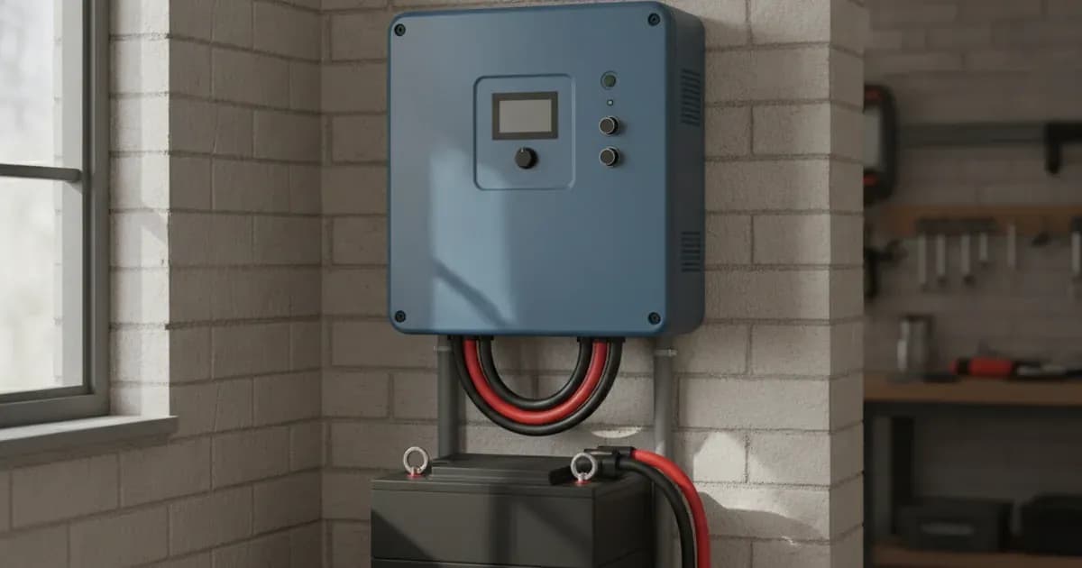
The Victron ECOmulti Hub-2 system integrates several key Victron components into one smart housing, including a MultiPlus 24/3000/70-50 inverter/charger, a VE.Bus BMS, and a Color Control GX (CCGX). Proper installation involves careful handling due to its weight, correct battery and AC sensor connections, and specific software configurations.
Installation Steps
Follow these steps to correctly install your Victron ECOmulti system.
- Unpack and Mount the ECOmulti Unit
- The ECOmulti unit weighs approximately 60 kg. Ensure you have adequate support and assistance for safe handling and mounting.
- Choose a suitable location, considering ventilation and accessibility for future maintenance.
- Connect the Batteries
- Before connecting, verify the voltage of each battery. Each battery should have about 13.3VDC.
- Interconnect the BMS cables of your batteries in a chain.
- Connect the chained BMS cables to the VE.Bus BMS located inside the ECOmulti.
- When making the final battery connection, be aware that this step will produce electrical sparks due to the inductance in the ECOmulti. This is normal, and nothing will be destroyed.
- Install and Connect the AC Current Sensor
- Mount the Color Control GX (CCGX) display at a height of 170cm above the floor for optimal visibility and interaction.
- The AC current sensor's green connector is polarized. The brown wire is plus, and the blue wire is minus.
- Connect the AC current sensor to the T-Sense input of the ECOmulti: the brown wire (plus) goes to the left side, and the blue wire (minus) goes to the right side.
- Set the DIP switches on the AC current sensor for the 3,000W range, which is appropriate for a 2,88kWp plant.
- Connect to Mains and Solar System
- Install a transfer switch S1 with 35A between the input and output of the ECOmulti to close the phase L2 in case of an ECOmulti failure. In normal operation, this switch must be open.
- An extra fuse F5/16A is required to protect the solar system.
- Note that on the L2 output of the ECOmulti, another electronic fuse 35A is mounted to prevent damage to the ECOmulti in case of a short in the house.
Configuration Settings
After physical installation, configure the ECOmulti's software components.
Component | Setting Name | Value | Notes |
|---|---|---|---|
VEConfigure 3 | Version | Rev. 90.04.169 | Ensure this specific version is used for configuration. |
ECOmulti | Firmware | 2610304 | Verify the ECOmulti is running this firmware version. |
Color Control GX | Version | rev. 1.14 | Confirm the CCGX is updated to this version. |
AC current sensor | DIP switches | Set for the 3,000W range | For a 2,88kWp plant, adjust DIP switches accordingly. |
Troubleshooting Common Issues
Symptom detail | Likely cause | Fix |
|---|---|---|
ECOmulti failure | Short in the house | Identify and resolve the short circuit in the house wiring. |
Display value of AC sensor is zero | Phase and neutral are both used through the current sensor | Ensure only the phase wire (or neutral, but not both) passes through the current sensor. Re-route wiring as needed. |
Safety: Handling the ECOmulti System
The Victron ECOmulti system involves high voltages and significant weight. Always prioritize safety during installation and maintenance.
- Weight: The ECOmulti unit weighs approximately 60 kg. Use proper lifting techniques and ensure secure mounting to prevent injury or damage.
- Battery Connections: The final battery connection will produce electrical sparks due to inductance. While this is normal, ensure no flammable materials are nearby.
- Mains Connection: The system involves mains voltage. Ensure the transfer switch S1 (35A) is correctly installed and operated. The electronic fuse 35A on the L2 output provides protection against shorts in the house.
- Solar System Protection: An extra fuse F5/16A is necessary to protect the solar system components.
- Maintenance: For maintenance work, always switch off the main fuse L2, the output fuse L2, and the solar fuse 16A to isolate the ECOmulti.
When to call a technician instead
While many installation steps can be performed by a competent DIYer, certain situations warrant professional assistance. You should call a qualified technician if:
- You are unsure about any aspect of the AC mains wiring or connection.
- You encounter persistent ECOmulti failures that cannot be resolved by addressing simple short circuits.
- The AC sensor consistently reads zero despite correct wiring and DIP switch settings, indicating a potential internal fault.
- You are uncomfortable working with high-voltage electrical systems or the weight of the ECOmulti unit.
- Any internal component of the ECOmulti appears damaged or requires replacement, as opening the unit may void warranties or require specialized tools and knowledge.
Frequently asked questions
What components are integrated into the Victron ECOmulti system?
The ECOmulti integrates a MultiPlus 24/3000/70-50 inverter/charger, a VE.Bus BMS, a Color Control GX (CCGX), a fuse holder with a MEGA-fuse 300A 32V, and all necessary internal cabling.
What is the weight of the ECOmulti unit?
The ECOmulti unit weighs approximately 60 kg, requiring careful handling during installation.
How should the AC current sensor be connected to the ECOmulti?
The AC current sensor's green connector is polarized. The brown wire (plus) connects to the left side of the T-Sense input, and the blue wire (minus) connects to the right side.
What firmware and software versions are used with the ECOmulti?
The ECOmulti uses firmware version 2610304. VEConfigure 3 should be Rev. 90.04.169, and the Color Control GX (CCGX) should be version rev. 1.14.
Is it normal to see a spark when connecting the battery to the ECOmulti?
Yes, the last step of battery connection will produce electrical sparks due to the inductance in the ECOmulti. This is normal and will not damage the unit.
References
- Victron Energy ECOmulti Manual/Datasheet — accessed 23 August 2026
Related guides
More from what to buy — and how not to get cheated.