Victron VE.CAN Resistive Tank Sender Adapter Troubleshooting
Updated 10 September 2026 · By SolarNevs Research Desk, Dealer surveys + verified sources · 1 source · Method ↗
Key Takeaways
- The most common issues are incorrect rotary switch settings or problems with the VE.Can network.
- Always start by verifying the rotary switch settings match your tank sender type and fluid.
- Ensure all power is disconnected from the system before making any wiring changes to prevent electrical hazards.
- If network communication issues persist after checking cables and terminators, consult a qualified technician.
Why is my Victron VE.Can Tank Sender Adapter not showing tank levels?
The most common cause for a Victron VE.Can Resistive Tank Sender Adapter not displaying tank levels is incorrect configuration of its rotary switch or issues with the VE.Can network connection. First, verify that the rotary switch settings on the adapter correctly match your tank sender's resistance standard and the type of fluid in the tank.
Diagnosis
Follow these steps to diagnose why your VE.Can Resistive Tank Sender Adapter might not be working correctly.
- Check Power to the Adapter:
- Observable Check: The adapter does not have indicator LEDs mentioned in its manual. Instead, you must verify the input voltage.
- What it means: The adapter requires an input voltage between 9 and 70 VDC. If it is not receiving power, it cannot function.
- Action: Use a multimeter to measure the voltage at the power input terminals of the adapter. Ensure the voltage is within the specified range. If powered via the VE.Can network, verify the network power source is active.
- Verify VE.Can Network Connection:
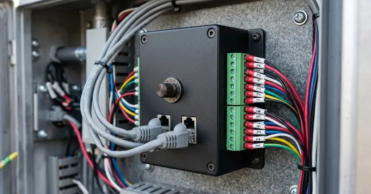
- Observable Check: The adapter connects to the VE.Can network using standard straight RJ-45 cables. It has two RJ-45 sockets for daisy-chaining.
- What it means: A faulty cable, missing terminators, or an unpowered network will prevent the adapter from communicating with your Victron GX device (e.g., Color Control GX). The VE.Can network requires a terminator at both ends.
- Action:
- Ensure RJ-45 cables are securely connected to both sockets if daisy-chaining.
- Confirm that VE.Can terminators are installed at the physical ends of your VE.Can network.
- Verify that a compatible Victron product (e.g., Skylla-i, Lynx Ion + Shunt, BlueSolar MPPT 150/70 VE.Can) is powering the VE.Can network, or that a dedicated VE.Can Power Cable (ASS030690000) is used if no compatible product is present.
- Inspect Rotary Switch Settings:
- Observable Check: The adapter features a rotary switch for configuration.
- What it means: Incorrect settings for sender resistance type, tank type, or tank instance will lead to inaccurate readings or no display on your GX device. The adapter supports European standard 0-180 Ohm and American 240-30 Ohm senders.
- Action:
- Identify your tank sender's resistance standard (European 0-180 Ohm or American 240-30 Ohm).
- Select the correct tank type (e.g., Fuel, Fresh Water, Waste Water, Oil, Live Well, Black Water) using the rotary switch. Refer to the adapter's manual for specific switch positions (0-5 for European, 8-D for American).
- If you have multiple tank sender adapters, ensure each has a unique Tank Instance number set via its rotary switch.
- Check Resistance Sender Wiring:
- Observable Check: The adapter has two spring-loaded terminals for the tank sender wires.
- What it means: Loose, corroded, or incorrectly wired sender connections will prevent the adapter from receiving the resistance signal from the tank sender.
- Action:
- Ensure the two wires from your tank sender are securely connected to the adapter's spring-loaded terminals.
- Check for any signs of corrosion or damage on the wires or terminals.
- Review Color Control GX Configuration:
- Observable Check: The adapter appears as a new entry on the main menu of the Color Control GX. The current tank level and remaining capacity are displayed on the tank page.
- What it means: While the rotary switch handles primary configuration, some settings like Capacity, Fluid type, and Volume unit are configurable via the Color Control GX. Incorrect settings here can lead to misinterpretation of the tank level. The adapter does not accept custom names, using instances for distinction.
- Action:
- Navigate to the tank page on your Color Control GX.
- Verify that the displayed tank type and capacity settings align with your physical tank. Adjust these settings as needed.
Cause/Fix Table
Symptom detail | Likely cause | Fix |
|---|---|---|
Adapter not visible on GX device or no tank level displayed | No power to adapter | Verify input voltage is 9 to 70 VDC at the adapter terminals. Ensure VE.Can network power source is active. |
Adapter not visible on GX device or no tank level displayed | VE.Can network communication issue | Check all RJ-45 cables for secure connection. Confirm VE.Can terminators are present at both ends of the network. |
Incorrect tank level readings or unexpected tank type | Incorrect rotary switch setting for sender resistance | Adjust rotary switch to match your tank sender's standard: 0-180 Ohm (European) or 240-30 Ohm (American). |
Incorrect tank level readings or unexpected tank type | Incorrect rotary switch setting for tank type | Set the rotary switch to the correct tank type (e.g., Fuel, Fresh Water, Waste Water) as per the manual's switch positions. |
Multiple tanks not displaying correctly or conflicting | Duplicate Tank Instance numbers | For each adapter in a multi-tank system, set a unique Tank Instance number using its rotary switch. |
Tank level stuck or erratic | Loose or corroded sender wiring | Securely connect tank sender wires to the adapter's spring-loaded terminals. Inspect wires for damage or corrosion. |
Tank level displayed but capacity/units are wrong | Incorrect configuration in Color Control GX | Adjust Capacity, Fluid type, and Volume unit settings via the Color Control GX menu for the specific tank. |
Configuration and Network Setup Details
The Victron VE.Can Resistive Tank Sender Adapter is designed for straightforward setup, primarily through its rotary switch and integration into the VE.Can network. Understanding these details is key to proper operation.
Rotary Switch Configuration The adapter's rotary switch is central to its configuration. It allows you to select both the type of resistive tank sender and the fluid type of the tank.
- Sender Resistance: The adapter suits European standard 0-180 Ohm and American 240-30 Ohm senders. You must select the correct range on the rotary switch to ensure accurate readings.
- Tank Type: The switch allows you to specify the tank's contents, with options for Fuel (Switch Position 0 for European, 8 for American), Fresh Water (Position 1 for European, 9 for American), Waste Water (Position 2 for European, A for American), Live well (Position 3 for European, B for American), Oil (Position 4 for European, C for American), or Black water (Position 5 for European, D for American). This ensures the GX device interprets the data correctly.
- Tank Instance: For systems with multiple tanks, each adapter must be assigned a unique Tank Instance number via the rotary switch. This allows the GX device to distinguish between different tanks, supporting up to 16 tanks of the same type in one network.
VE.Can Network Connection The adapter integrates into a VE.Can network, which is Victron's implementation of the CAN bus protocol.
- Physical Connection: The adapter features two RJ-45 sockets, allowing for easy daisy-chaining using standard straight RJ-45 cables.
- Network Termination: Proper network termination is critical for VE.Can communication. A VE.Can terminator must be installed at both physical ends of the network to prevent signal reflections.
- Powering the Network: The adapter draws its power from the VE.Can network. This power can be supplied by compatible Victron products such as the Skylla-i, Lynx Ion + Shunt, Lynx Shunt VE.Can, BlueSolar MPPT 150/70 VE.Can, or BlueSolar MPPT 150/85 VE.Can. If no such product is available on the network, a dedicated VE.Can Power Cable (ASS030690000) is required to supply the necessary 9 to 70 VDC. The adapter itself has an under 50mA power usage.
Color Control GX Interaction Once properly connected and configured via the rotary switch, the adapter will appear as a new entry on the main menu of a connected Color Control GX. The current tank level and remaining capacity are then displayed on the tank page. While the rotary switch handles the primary settings, further fine-tuning of parameters like Capacity, Fluid type, and Volume unit can be performed through the Color Control GX interface. Note that the adapter does not support custom naming; it uses the instance number for distinction in multi-tank setups.
Safety
When working with any electrical system, including the Victron VE.Can Resistive Tank Sender Adapter, prioritize safety.
- Disconnect Power: Always ensure that all power sources, including batteries and any charging devices, are disconnected before performing any wiring or installation work on the adapter or its associated components. This prevents accidental short circuits or electrical shock.
- Voltage Range: The adapter operates within an input voltage range of 9 to 70 VDC. Ensure that any power source connected to the VE.Can network or directly to the adapter falls within this specified range.
- Insulated Tools: Use insulated tools when working with electrical connections to minimize the risk of short circuits.
- Wiring Integrity: Ensure all wiring connections are secure and free from damage or corrosion. Loose connections can lead to intermittent operation or create fire hazards.
When to call a technician instead
While many troubleshooting steps can be performed by the user, there are situations where professional assistance is recommended. You should call a qualified technician if:
- You have followed all diagnosis steps and the adapter still fails to function or communicate with your GX device.
- You suspect internal damage to the adapter or other Victron components.
- You are uncomfortable working with electrical systems or diagnosing complex network issues.
- You encounter persistent VE.Can network problems that cannot be resolved by checking cables and terminators.
- The issue involves components beyond the adapter itself, such as the tank sender or the GX device, and you lack the expertise to diagnose them.
Frequently asked questions
How do I configure the Victron VE.Can Tank Sender Adapter for my tank?
You configure the adapter using its rotary switch. This switch selects the sender resistance type (European 0-180 Ohm or American 240-30 Ohm) and the specific tank type (e.g., Fuel, Fresh Water, Waste Water). Ensure the switch position matches your sender and tank fluid.
What types of tank senders are compatible with the adapter?
The Victron VE.Can Resistive Tank Sender Adapter suits both European standard 0-180 Ohm and American 240-30 Ohm resistive tank senders. You select the appropriate standard and tank type using the adapter's rotary switch.
How do I connect the adapter to my VE.Can network?
The adapter connects to a VE.Can network using standard straight RJ-45 cables. It has two RJ-45 sockets for daisy-chaining. Ensure the network has terminators at both ends. The adapter requires power from a compatible VE.Can product or a dedicated VE.Can power cable.
Can I use multiple tank sender adapters in one system?
Yes, you can use multiple tank sender adapters in one network. The system supports up to 16 tanks of the same tank type. Each adapter requires a unique Tank Instance number, which is set via its rotary switch.
What is the power consumption of the Victron VE.Can Resistive Tank Sender Adapter?
The adapter has an under 50mA power usage. It operates with an input voltage range of 9 to 70 VDC.
References
- Victron VE.Can Resistive Tank Sender Adapter Manual — accessed 23 August 2026
Related guides
More from sizing, net billing & installation.