Setting up Your Victron VE.CAN Resistive Tank Sender Adapter
Updated 17 September 2026 · By SolarNevs Research Desk, Dealer surveys + verified sources · 1 source · Method ↗
Key Takeaways
- The Victron VE.Can Resistive Tank Sender Adapter integrates standard resistive tank senders with your Victron Color Control GX via the VE.Can network.
- Ensure proper VE.Can network termination and power supply for the adapter to communicate correctly.
- Tank type, sender resistance, and unique tank instance are set using the adapter's rotary switch.
- Always disconnect all power sources to your system before making any wiring connections to prevent electrical hazards.
How do I set up the Victron VE.Can Resistive Tank Sender Adapter?
Setting up the Victron VE.Can Resistive Tank Sender Adapter involves physically connecting your tank sender and the VE.Can network, then configuring the adapter using its rotary switch and your Color Control GX. The VE.Can resistive tank sender adapter allows a standard resistive tank level sender to connect to the Color Control GX.
Installation Steps
Follow these steps to install and configure your VE.Can Resistive Tank Sender Adapter:
- Safety First: Disconnect Power. Before making any electrical connections, ensure all power sources to your system (AC, DC, PV) are disconnected. This includes turning off breakers for batteries, solar arrays, and grid connections.
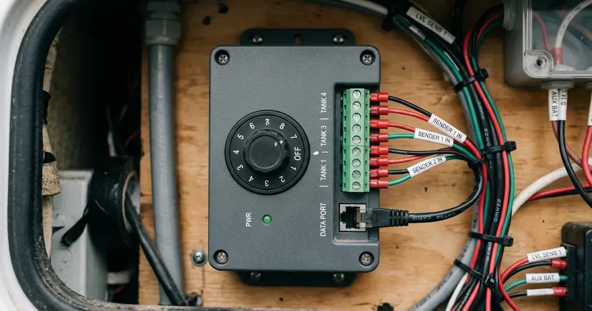
- Connect the Tank Sender. Locate the two wires from your resistive tank sender. Connect these two wires to the two spring loaded terminals on the VE.Can Resistive Tank Sender Adapter. The adapter suits European standard 0-180 Ohm and US standard 240-30 Ohm senders.
- Connect to the VE.Can Network. The adapter connects to your VE.Can network using a standard straight RJ-45 cable. The adapter has two RJ45 sockets for daisy chaining, allowing you to connect multiple VE.Can devices in series. Ensure that VE.Can terminators are present at both ends of your VE.Can network.
- Power the Adapter. The VE.Can Resistive Tank Sender Adapter is powered via the VE.Can network. It can be powered by compatible Victron products such as Skylla-i, Lynx Ion + Shunt, Lynx Shunt VE.Can, BlueSolar MPPT 150/70 VE.Can, or BlueSolar MPPT 150/85 VE.Can. If no compatible product is available to provide power, use a "VE.Can Power Cable - ASS030690000". The adapter has an input voltage range of 9 to 70 VDC and a power usage of under 50mA.
- Set Rotary Switch for Tank Type and Resistance. Use the rotary switch on the adapter to select the correct tank type and sender resistance. This switch allows you to choose between European standard (0-180 Ohm) or US standard (240-30 Ohm) senders, and specify the tank's contents.
- Set Rotary Switch for Tank Instance (for multiple tanks). If you are monitoring multiple tanks, each VE.Can Resistive Tank Sender Adapter requires a unique Tank Instance number. Set this using the rotary switch. Up to 16 tanks of the same tank type can be monitored in one network.
- Configure on Color Control GX. Once physically connected and the rotary switch settings are made, navigate to the Color Control GX main menu, then the "tank page", and select the "Setup" item. Here, you can configure the tank's Capacity, Fluid type, and Volume unit.
Configuration Settings
The VE.Can Resistive Tank Sender Adapter uses a rotary switch for primary configuration and the Color Control GX for fine-tuning.
Setting Name | Values | Rotary Switch Position / Color Control GX Menu |
|---|---|---|
Sender resistance (European) | 0-180 Ohm | Rotary switch position 0-5 |
Sender resistance (American) | 240-30 Ohm | Rotary switch position 8-D |
Tank Type (European) | Fuel | Rotary switch position 0 |
Tank Type (European) | Fresh Water | Rotary switch position 1 |
Tank Type (European) | Waste Water | Rotary switch position 2 |
Tank Type (European) | Live well | Rotary switch position 3 |
Tank Type (European) | Oil | Rotary switch position 4 |
Tank Type (European) | Black water | Rotary switch position 5 |
Tank Type (American) | Fuel | Rotary switch position 8 |
Tank Type (American) | Fresh Water | Rotary switch position 9 |
Tank Type (American) | Waste Water | Rotary switch position A |
Tank Type (American) | Live well | Rotary switch position B |
Tank Type (American) | Oil | Rotary switch position C |
Tank Type (American) | Black water | Rotary switch position D |
Tank Instance | Unique number for each tank in a multi-tank system | Rotary switch |
Capacity | Configurable on Color Control GX | Color Control GX menu |
Fluid type | Configurable on Color Control GX | Color Control GX menu |
Volume unit | Configurable on Color Control GX | Color Control GX menu |
Common Setup Issues and Checks
If your tank monitoring system is not working as expected, check these common issues:
Symptom detail | Likely cause | Fix |
|---|---|---|
Adapter not appearing on Color Control GX | Incorrect VE.Can network setup or no power. | Ensure VE.Can terminators are at both ends of the network. Verify the adapter is powered by a compatible Victron product or the 'VE.Can Power Cable - ASS030690000'. Check RJ-45 cable connections. |
Incorrect tank level readings | Rotary switch settings do not match the physical tank sender or tank type. | Verify the rotary switch is set to the correct sender resistance (e.g., European standard 0-180 Ohm or US standard 240-30 Ohm) and tank type (Fuel, Freshwater, etc.). Calibrate the tank Capacity on the Color Control GX. |
Multiple tanks not displaying correctly or showing duplicate readings | Duplicate Tank Instance settings on multiple adapters. | Ensure each VE.Can Resistive Tank Sender Adapter in a multi-tank system has a unique Tank Instance number set via its rotary switch. |
Safety: Electrical Connections
Working with electrical systems carries inherent risks. Always prioritize safety. Before connecting or disconnecting any wiring, ensure all power sources to your system are completely isolated. This includes turning off circuit breakers for solar panels, batteries, and grid connections. Use insulated tools to prevent accidental short circuits. The VE.Can Resistive Tank Sender Adapter has a robust ABS Construction sealed to IP67, but it is not designed to be opened or serviced internally by the user.
When to call a technician instead
While the VE.Can Resistive Tank Sender Adapter is designed to be easy to install, some situations may require professional assistance. If you have followed all installation and configuration steps and are still experiencing issues, or if you are uncomfortable working with electrical wiring, it is best to consult a qualified Victron Energy installer or technician. Attempting repairs or modifications beyond the scope of the manual may void your product warranty.
Frequently asked questions
What does the Victron VE.Can Resistive Tank Sender Adapter do?
The VE.Can resistive tank sender adapter allows a standard resistive tank level sender to connect to the Color Control GX. It provides high ±1% accuracy for tank level readings.
What types of tank senders are compatible with the adapter?
The adapter suits European standard 0-180 Ohm and US standard 240-30 Ohm senders. You select the appropriate standard using a rotary switch on the adapter.
How many tanks can I monitor with Victron VE.Can adapters?
For multiple tanks, you can use multiple tank sender adapters in one network. The system supports up to 16 tanks of the same tank type within a single VE.Can network.
How is the VE.Can Resistive Tank Sender Adapter powered?
The adapter is powered via the VE.Can network by compatible Victron products like Skylla-i or BlueSolar MPPTs. If no compatible product is present, you can use a 'VE.Can Power Cable - ASS030690000'.
How do I configure the tank type and resistance settings?
Tank type and sender resistance are configured using a simple rotary switch on the adapter itself. Tank types include Fuel, Freshwater, Wastewater, Oil, Live Well, or Blackwater, easily selectable.
References
- Victron Energy VE.Can Resistive Tank Sender Adapter Manual — accessed 23 August 2026
Related guides
More from sizing, net billing & installation.