Victron VE.Direct Protocol: Understanding Communication and Troubleshooting
Updated 9 September 2026 · By SolarNevs Research Desk, Dealer surveys + verified sources · 1 source · Method ↗
Key Takeaways
- Victron VE.Direct ports operate at specific voltage levels, either 3v3 or 5v, depending on the device model.
- Galvanically isolated interfaces, such as the VE.Direct to USB or VE.Direct to RS232, are recommended for stable connections.
- The VE.Direct port uses a four-pin configuration: positive, TX, RX, and GND.
- Always verify the correct voltage and pin configuration for your specific Victron product before attempting a connection to prevent damage.
What is Victron VE.Direct and how does it work?
VE.Direct is Victron Energy's proprietary communication protocol, designed to allow Victron products to communicate with each other and with external devices for monitoring and control. It is a serial communication protocol that uses specific voltage levels and pin configurations. Understanding these specifics is crucial for successful integration and troubleshooting.
Diagnosing VE.Direct Communication Issues
Successful VE.Direct communication relies on correct voltage, pin configuration, and interface selection. Follow these steps to diagnose common issues.
Step 1: Identify Your Victron Device Model and VE.Direct Voltage
Different Victron products use different VE.Direct voltage levels. Incorrect voltage can prevent communication or damage your device.
- Check your device model: Locate the model name on your Victron product.
- Determine the required VE.Direct voltage:
- 3v3 devices: BMV-700, MPPT RS, Multi RS, any other RS models, VE.Direct Inverters 250…500VA, VE.Direct Inverters 800VA & 1200VA, and Smart Inverters 1600VA...5000VA.
- 5v devices: Most MPPT models. Newer MPPTs (under development) also use 5V.
Step 2: Select the Correct Interface
Victron recommends using specific interfaces for direct connection to a VE.Direct port. These interfaces include galvanic isolation, which helps prevent ground loops and electrical interference.
- VE.Direct to USB interface: Recommended for connecting to a computer's USB port.
- VE.Direct to RS232 interface: Recommended for connecting to an RS232 port. This interface has part number ASS030520500.
Step 3: Verify VE.Direct Port Pin Configuration
The VE.Direct port on Victron devices has four pins. Ensure your connecting cable or interface aligns with these pins:
- Positive
- TX (Transmit)
- RX (Receive)
- GND (Ground)
Step 4: Check VE.Direct to RS232 Interface Power and Pinouts
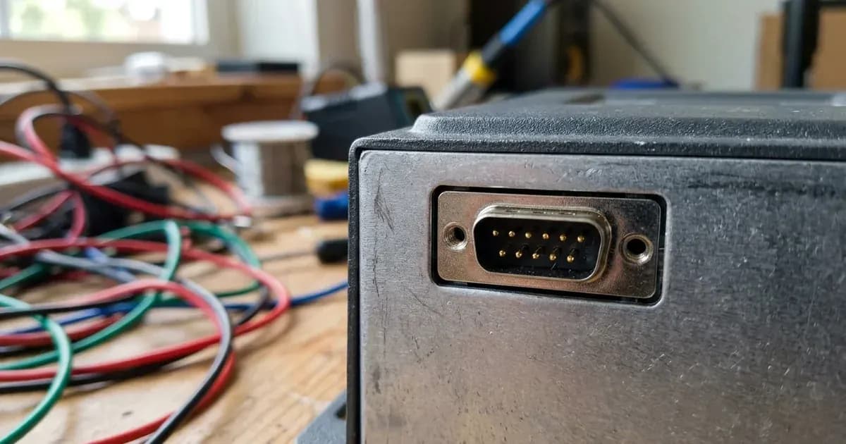
If you are using a VE.Direct to RS232 interface, specific power and pin configurations are required for the DB9 connector.
- Communication pins: For communication, use the GND, RX, and TX pins: pin 5, 2, and 3 on the DB9 connector.
- Powering the interface: The DTR signal (pin 4 on the DB9 connector) and/or the RTS signal (pin 7 on the DB9 connector) must be driven high to power the isolated side of the interface.
- DTR logic: Most RS232 drivers are inverting, so the logic level of the DTR must be programmed to zero in most cases.
- External power: When using an external power supply to power DTR or RTS, the minimum voltage is 5V, and the maximum is 12V.
VE.Direct Communication Troubleshooting Table
Symptom detail | Likely cause | Fix |
|---|---|---|
Communication failure | Incorrect VE.Direct voltage for the device | Verify your device model and its required VE.Direct voltage (3v3 or 5v) from the models table above. |
No data from device via RS232 | VE.Direct to RS232 interface not powered correctly | Ensure the DTR signal (pin 4 on DB9) and/or RTS signal (pin 7 on DB9) are driven high. If using external power, ensure it's between 5V and 12V. |
Intermittent or unreliable communication | Lack of galvanic isolation in the connection | Use a recommended VE.Direct to USB or VE.Direct to RS232 interface, as these include galvanic isolation. |
No data from RS232 interface | Incorrect pin connections on the DB9 connector | Connect GND to pin 5, RX to pin 2, and TX to pin 3 on the DB9 connector. |
HEX commands not being processed | Incorrect end-of-line character in HEX messages | The end of line character for HEX messages is ' ' (Line feed, LF, ASCII character 10). Ensure this is used. |
Device stops sending TEXT frames after HEX command | Expected behavior when sending HEX messages | After receiving a HEX message, the Victron product will stop sending its usual TEXT frames for a few seconds. This is normal operation. |
Understanding VE.Direct Protocol Basics
The VE.Direct protocol facilitates data exchange between Victron devices and other systems. It supports both TEXT and HEX (binary) frames for communication.
Data Communication
- TEXT frames: These are typically used for status updates and monitoring data.
- HEX frames: These are used for more specific commands or data requests. When a Victron product receives a HEX message, it will temporarily stop sending its usual TEXT frames for a few seconds.
- HEX message frequency: There is no minimum frequency for sending HEX messages; you can send them as often or as seldom as needed.
- End of line character: For HEX messages, the end of line character is '\n', also known as Line feed (LF) or ASCII character 10.
Current Draw
The VE.Direct port itself has a low power consumption. It draws a maximum average of 10mA, with short bursts of up to 20mA for 5ms. This low power draw makes it suitable for continuous operation without significantly impacting the device's overall power consumption.
Safety: Electrical Connections
When working with any electrical system, including VE.Direct connections, safety is paramount.
- Galvanic Isolation: Always use interfaces that provide galvanic isolation, such as the recommended VE.Direct to USB or VE.Direct to RS232 interfaces. This protects your connected equipment from potential electrical surges or ground loops.
- Voltage Verification: Double-check the required VE.Direct voltage for your specific Victron device before connecting any interface. Applying an incorrect voltage can damage the device.
- Power Down: Before making or breaking any electrical connections, ensure that the Victron device and any connected power sources are turned off and de-energized.
- Insulated Tools: Use insulated tools when working with electrical terminals to prevent accidental short circuits.
- Current Draw: While the VE.Direct port's current draw is low (max 10mA average, with max 20mA/5ms bursts), ensure your interface can handle this without issues.
When to call a technician instead
While many VE.Direct communication issues can be resolved with careful diagnosis, there are situations where professional assistance is necessary.
- Persistent Communication Failure: If you have followed all troubleshooting steps and still cannot establish reliable communication, there may be an internal fault with the Victron device or the interface.
- Physical Damage: If the VE.Direct port on your Victron device appears physically damaged, do not attempt further DIY repairs. This could void your warranty or cause further damage.
- Uncertainty with Wiring: If you are unsure about any wiring or electrical connections, especially when dealing with external power supplies for RS232 interfaces, it is safer to consult a qualified electrician or Victron service technician.
- Warranty Concerns: Attempting unauthorized repairs or modifications to your Victron device may void its warranty. If your device is still under warranty, contact Victron Energy support or an authorized service center.
Frequently asked questions
What is the VE.Direct port voltage for Victron devices?
The VE.Direct port voltage varies by device. For example, the BMV-700, MPPT RS, Multi RS, and VE.Direct Inverters (250-1200VA, Smart Inverters 1600-5000VA) use 3v3. Most MPPT models use 5v.
How do I connect to a VE.Direct port?
Victron recommends using a VE.Direct to USB interface or a VE.Direct to RS232 interface for direct connection. Both interfaces include galvanic isolation for reliable communication.
What are the pins on a VE.Direct port?
A VE.Direct port typically has four pins: positive, TX (transmit), RX (receive), and GND (ground).
What is the maximum current draw of a VE.Direct port?
The VE.Direct port has a maximum average current draw of 10mA, with bursts up to 20mA for 5ms.
How do I power the VE.Direct to RS232 interface?
The isolated side of the VE.Direct to RS232 interface requires power. This is typically supplied by driving the DTR signal (pin 4 on the DB9 connector) and/or the RTS signal (pin 7 on the DB9 connector) high. An external power supply between 5V and 12V can also be used.
References
- Victron Energy VE.Direct Protocol FAQ — accessed 23 August 2026
Related guides
More from sizing, net billing & installation.