Victron GX GSM: Cellular Modem & GPS Setup
Updated 16 September 2026 · By SolarNevs Research Desk, Dealer surveys + verified sources · 1 source · Method ↗
Key Takeaways
- The GX GSM is a modem and GPS accessory for our GX range of monitoring products.
- Model lineup coverage: GX GSM GSM100100100 | GSM100200100.
- Direct battery power span: Supply voltage range 8 - 70VDC.
- Host USB connectivity: Fixed 1.0m cable with USB-A connector (connects to the GX device).
- Complete power wiring harness: Power cable (included) 1.4m cable with inline fuse holder, terminal block and 10mm ring terminals.
- Overcurrent fuse protection: Inline fuse (included) T3.15A250V.
- Heavy-duty DC cable specification: A 1.4 m cable with M10 cable lugs and a built-in Slow Blow fuse 3.15A 250V, 5x20mm is included.
- Satellite location tracking: The GX GSM includes a built-in GPS receiver..
- External active GPS antenna: The required accessory part number is GSM900200100 - Active GPS Antenna for GX GSM.
- RF antenna interface: LTE antenna connector Type SMA Female.
- Broad thermal operating span: Operating temperature range -40 +50°C (-40 - 120°F).
Cellular Modem Architecture & GX Controller Integration
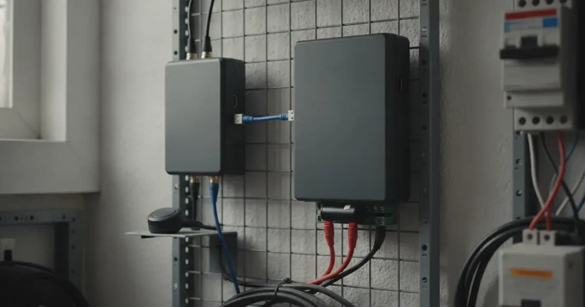
The GX GSM provides cellular internet connectivity and GPS tracking for Victron GX controllers (Cerbo GX, Venus GX) in mobile or remote off-grid locations. Powered directly from the system battery bank, it ensures continuous telemetry streaming to the VRM cloud portal.
The Victron GX GSM (GSM100100100 | GSM100200100) provides cellular and GPS connectivity across an 8 - 70VDC supply range with a fixed 1.0m USB-A cable for GX controllers:
- DC Power Input: 8 - 70VDC Range, 1.4m Cable Harness, M10 Ring Terminals, T3.15A 250V Fuse.
- Cellular & GPS RF: Built-in GPS Rec., SMA Female GSM, GSM900200100 GPS, -40 to +50°C Env.
- Host Interface: 1.0m USB-A, Venus OS Auto, VRM Telemetry, SMS Alarms.
Installation Rules & Power Connection
- USB Host Connection: Connect the Fixed 1.0m cable with USB-A connector (connects to the GX device) into any vacant USB port on the GX device.
- Battery Supply Harness: Connect the Power cable (included) 1.4m cable with inline fuse holder, terminal block and 10mm ring terminals across Supply voltage range 8 - 70VDC, ensuring Inline fuse (included) T3.15A250V is seated where A 1.4 m cable with M10 cable lugs and a built-in Slow Blow fuse 3.15A 250V, 5x20mm is included.
- Antenna Termination: Connect the cellular rod antenna to the LTE antenna connector Type SMA Female.
GPS Geofencing & VRM Cloud Telematics
The GX GSM combines cellular connectivity with satellite fleet management:
- Integrated Satellite Receiver: Incorporates real-time tracking since The GX GSM includes a built-in GPS receiver. when paired with The required accessory part number is GSM900200100 - Active GPS Antenna for GX GSM.
- Operating Envelope: Functions reliably across Operating temperature range -40 +50°C (-40 - 120°F).
- System Telemetry: Operates as The GX GSM is a modem and GPS accessory for our GX range of monitoring products across all GX GSM GSM100100100 | GSM100200100 hardware.
Technical Specifications & Sizing Summary
Parameter | Engineering Rating | Design Significance |
|---|
Model Hierarchy Part Numbers | GX GSM GSM100100100 | GSM100200100 | Cellular modem hardware variants |
System Monitoring Role | The GX GSM is a modem and GPS accessory for our GX range of monitoring products | Dedicated cellular and tracking expansion for GX devices |
DC Input Operating Span | Supply voltage range 8 - 70VDC | Connects directly across battery systems within 8 to 70VDC |
Host USB Interface | Fixed 1.0m cable with USB-A connector (connects to the GX device) | Plug-and-play USB connection recognized by Venus OS |
DC Power Cable Harness | Power cable (included) 1.4m cable with inline fuse holder, terminal block and 10mm ring terminals | Complete pre-assembled battery connection harness |
Inline Overcurrent Fuse | Inline fuse (included) T3.15A250V | Protects power supply cable against dead short circuits |
Detailed Harness Sizing | A 1.4 m cable with M10 cable lugs and a built-in Slow Blow fuse 3.15A 250V, 5x20mm is included | Heavy 5x20mm slow-blow ceramic fuse specification |
Integrated GPS Module | The GX GSM includes a built-in GPS receiver. | Real-time vehicle and boat position tracking |
Optional Active GPS Antenna | The required accessory part number is GSM900200100 - Active GPS Antenna for GX GSM | External active antenna for VRM geofencing |
Cellular Antenna Port | LTE antenna connector Type SMA Female | Standard 50-ohm RF connector for indoor/outdoor antennas |
Thermal Operating Span | Operating temperature range -40 +50°C (-40 - 120°F) | Rugged temperature envelope for engine compartments |
Add a battery at a surveyed price
Installers quote supply and fitting of the battery on this page for your existing or new system.
How this pays for the site: installers pay SolarNevs a fixed introduction fee when we pass them a genuine enquiry. They cannot pay to appear higher, and our surveyed prices are published before any introduction. You can also take our dated price tables straight to any installer.
Frequently asked questions
What models, operating voltage range, and system monitoring roles apply to GX GSM?
Covered by **GX GSM GSM100100100 | GSM100200100**, **The GX GSM is a modem and GPS accessory for our GX range of monitoring products** operating across **Supply voltage range 8 - 70VDC** (August 2026).
What cables, protective fuses, and antenna connections are supplied?
It provides **Fixed 1.0m cable with USB-A connector (connects to the GX device)**, **Power cable (included) 1.4m cable with inline fuse holder, terminal block and 10mm ring terminals** with **Inline fuse (included) T3.15A250V** where **A 1.4 m cable with M10 cable lugs and a built-in Slow Blow fuse 3.15A 250V, 5x20mm is included**, and an **LTE antenna connector Type SMA Female** (August 2026).
What GPS tracking capabilities and operating thermal ranges are supported?
**The GX GSM includes a built-in GPS receiver.** where **The required accessory part number is GSM900200100 - Active GPS Antenna for GX GSM**, operating across **Operating temperature range -40 +50°C (-40 - 120°F)** (August 2026).
References
- Victron Energy: GX GSM Manual — accessed 31 August 2026
Related guides
More from what to buy — and how not to get cheated.