Solar Battery Not Discharging: Inverter Not Using Battery Fix
Updated 6 September 2026 · By SolarNevs Research Desk, Dealer surveys + verified sources · 6 sources · Method ↗
Key Takeaways
- Inverter Output Source Priority set to Utility-first (USB) prevents battery discharge when grid power is present; switch Program 01 to SBU mode.
- Programmable SOC thresholds (Deye documents Shutdown 10-20% and Restart 40-50%) prevent battery discharge until capacity recovers above the restart threshold.
- Lithium BMS "Discharge MOS Off" protection halts discharge during under-voltage (2.50 V absolute limit, 2.8-3.0 V setpoint), overcurrent, or out-of-window pack temperatures (the 0-55°C charge / -10-55°C discharge figures are pack-temperature limits; charging below 0°C causes permanent lithium plating, so the cutoff is protection, not a fault).
- Heavy voltage sag on aged or sulfated lead-acid banks trips the inverter low DC cutoff (42.0 V is the Axpert default on a 48V bank, range 42-48 V; charge setpoints are referenced to 25°C with -3 to -5 mV/cell/°C temperature compensation in ambient heat) under load; kill power first and use insulated tools around terminals as a short draws hundreds of amps.
Why is my solar inverter not discharging the battery?
While our related diagnostic guide addresses solar batteries not charging, a solar battery that refuses to discharge represents the opposite operational challenge: energy is stored in the battery bank, but the inverter continues drawing power from the utility grid or shuts down entirely during load-shedding.
Working from the inverter manuals themselves — Voltronic's Axpert series, Growatt's SPF 5000 ES range, and Deye's hybrid documentation — five causes cover almost every case we see: an output source priority that puts utility power first (grid bypass mode), restrictive low-voltage or SOC cutoff limits, a tripped DC breaker or blown fuse, a BMS discharge protection lockout on a lithium pack, or severe voltage collapse on an aged lead-acid string.
Step-by-step diagnosis and non-discharging resolution
Follow these sequential diagnostic steps to restore battery discharging:
- Verify Inverter Output Source Priority (Program 01):
- Action: Access the inverter programming menu and inspect Program 01 (Output Source Priority).
- Factory Default Problem: On Voltronic Axpert units — and on the Inverex, Fronus, Knox, and Crown models rebadged from that platform — Program 01 leaves the factory set to "USB" (Utility, Solar, Battery). Under USB, whenever utility grid power is present the inverter powers AC loads entirely from the grid and treats the battery as a last resort. That is the design, not a fault.
- Remedy: Change Program 01 to "SBU" (Solar first, Battery second, Utility last) so the bank actually carries your evening load.
- Inspect SOC Cutoff and Restart Thresholds:
- Action: Check the battery discharge cutoff parameters in your inverter settings.
- Deye / Hybrid Logic: Deye's hybrid manual documents three SOC settings — Shutdown (10-20%), Low Batt (20-35%), and Restart (40-50%). Once the pack falls to the Shutdown figure the inverter stops using battery power, and output only resumes once solar or grid charging lifts it back above the Restart figure. A bank stranded between the two thresholds looks "charged but ignored".
- Voltronic / Off-Grid Cutoffs: Check Program 29 (Low DC Cutoff Voltage), which the Axpert ships at 42.0 V on a 48V system (range 42-48 V; note that all charge setpoints are referenced to 25°C, with -3 to -5 mV/cell/°C temperature compensation required in ambient heat). Set near the top of that range, the inverter stops discharging while the bank still holds usable capacity.
- Inspect DC Breaker and Fuse Continuity:
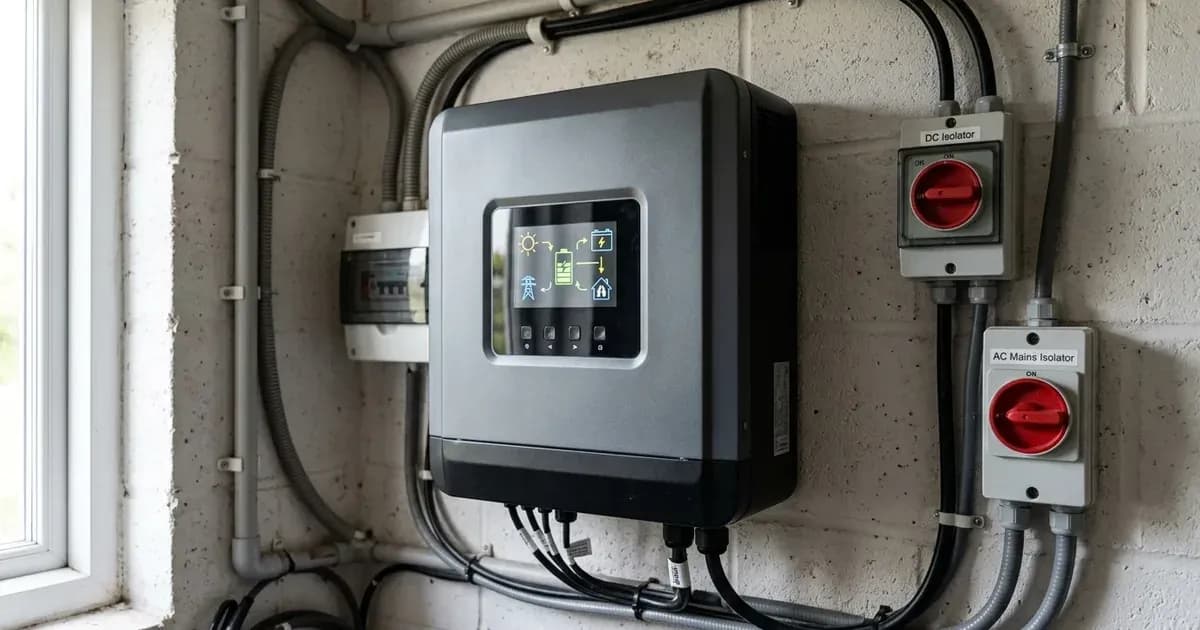
- Action: Inspect the DC circuit breaker and inline DC fuses between battery bank and inverter.
- Safety Precaution: Kill power first and use an insulated tool whenever inspecting or tightening battery terminals or DC isolators, because a metal spanner across a bank shorts hundreds of amps.
- Result: If the breaker has tripped or a fuse has blown, the inverter cannot detect or draw power from the battery. Measure DC voltage on both the battery side and inverter side of the isolator.
- Diagnose Lithium BMS Protection (Discharge MOS Off):
- Action: Check the front status LEDs on your lithium battery pack.
- Trigger: On Pylontech's US series — the family with a published LED table — a flashing red ALM LED means an alarm (a parameter is nearing its limit but the battery keeps working), while a solid red ALM with the other LEDs dark means protection: the pack refuses to charge or discharge until the condition clears. Your app may report the same state as "Discharge MOS Off".
- Typical thresholds (your BMS datasheet governs): LiFePO4 cells sit at an absolute under-voltage limit of 2.50 V, with common setpoints of 2.8-3.0 V; overcurrent and short-circuit trips are set per pack and are rarely published. Pylontech's US5000 datasheet gives a 0-55°C charge window and a -10-55°C discharge window, so a hot afternoon rack or a cold morning can legitimately lock discharge out.
- Remedy: Disconnect heavy loads, let the pack return to its rated window, then power-cycle the battery once the cause is cleared — that is the documented recovery from a protection state.
- Test Lead-Acid Voltage Sag Under Load:
- Action: Measure tubular battery terminal voltage at rest, then watch the same reading as you switch a real household load on. Always wear eye protection when testing electrolyte or inspecting cells, and add distilled water only, never acid.
- Reference point: On Osaka's published rested open-circuit ladder, 12.6 V+ (or 1.260 specific gravity) per 12V unit represents 100% full capacity, whereas 11.80 V (or 1.120 SG) is flat (0% capacity; all charging setpoints are referenced to 25°C with -3 to -5 mV/cell/°C temperature compensation in ambient heat).
- Symptom: If a rested bank that measured full collapses toward the 42.0 V cutoff (Axpert default 42.0 V, range 42-48 V) the moment loads turn on, the battery is the problem — severe sulfation, high internal resistance, or one dead cell dragging the string down.
Cause and Fix Matrix: Solar Battery Not Discharging
Displayed Symptom | Root Cause | Inverter Setting / Hardware Check | Exact Remedy |
|---|---|---|---|
Inverter uses grid instead of battery at night | Program 01 set to "USB" (Utility first) | Program 01 Output Source Priority | Change Program 01 to "SBU" (Solar-Battery-Utility). |
Inverter drops AC output mid-outage although the battery showed charge | Bank sags below the low DC cutoff under load | Program 29 Low DC Cutoff (Axpert default 42.0 V, range 42-48 V; setpoints referenced to 25°C with -3 to -5 mV/cell/°C temperature compensation) | Return Program 29 to its 42.0 V default if someone raised it; if it is already at default, the bank itself is sagging and needs service or replacement. |
Hybrid inverter stops discharging at a fixed percentage | Reached Shutdown SOC and is waiting for Restart SOC | Deye Shutdown SOC (10-20%) and Restart SOC (40-50%) | Normal behaviour. Discharge resumes only once charging lifts the pack above the Restart figure. |
Inverter reports a battery communication fault | Comms loss makes the inverter treat the battery as absent and fall back to the grid | RJ45 CAN/RS485 cable, correct port, matching protocol code | Restore the comms cable, or switch Program 05 to a manual User-Defined battery type. Deye shows this as F58; the Growatt "Warning 20" and Inverex/Knox "BMS lost" wordings come from a single local installer source, so treat those exact strings as indicative. |
Zero battery current; no voltage at the inverter DC terminals | Tripped DC breaker or blown battery fuse | External DC isolator and inline DC fuse (kill power first and use insulated tools) | Reset the DC circuit breaker or replace the blown DC fuse. |
Sizing and High-Load Discharge Realities
When discharging battery systems under heavy residential loads:
- Lithium Rack Module Sizing and BMS Overcurrent: A 48V LiFePO4 rack module such as the Pylontech US5000 (4.8kWh/100Ah) or US3000C (3.55kWh/74Ah) is BMS-managed. When residential load exceeds the continuous discharge capability of an individual module, the BMS opens its solid-state switches on an overcurrent trip (or overcurrent under BMS protection). Rather than overloading a single pack, stack modules in parallel (stackable to ~16 modules/string) to safely distribute heavy discharge currents.
- Lead-Acid Tubular Capacity and Voltage Sag: Flooded tall tubular batteries in Pakistan (Tall tubular TA/HT/TX/PowerLead class) are characterized at extended discharge rates. Drawing rapid discharge through an undersized or aged bank causes heavy terminal voltage sag, pulling the bank down to the inverter's Low-DC cutoff (Axpert default 42.0 V, range 42-48 V; referenced to 25°C with -3 to -5 mV/cell/°C temperature compensation in heat) and halting AC output.
For communication fault troubleshooting, consult our guide on lithium battery inverter compatibility errors. If the inverter shuts down without output, review inverter shows error but no output and our master inverter error code glossary.
Safety: Working with DC Battery Disconnects
Observe these mandatory safety protocols when troubleshooting battery discharge circuits:
- DC Arc Flash Danger & Terminal Safety: Kill power first and use insulated tools whenever working around DC battery terminals, because a metal spanner laid across two posts shorts hundreds of amps. Never open or close loose battery terminal connections under active load. Trip the DC circuit breaker before disconnecting battery cables, and disconnect the negative lead first.
- Electrolyte & Gassing Hazards: Flooded lead-acid gasses hydrogen on charge; electrolyte is sulfuric acid: wear eye protection, add distilled water only, never acid.
- Wait Before You Open Anything: Inverter capacitors hold lethal charge up to 5 minutes after shutdown, and PV conductors stay live whenever there is daylight on the array. Switch off, then wait.
- Mind the Weight: Tall tubular batteries run 55-73 kg each and are a genuine two-person lift; even a rack module like the Pylontech US5000 is 39.7 kg. Dropping one onto a live busbar becomes its own emergency.
When to call a technician instead
Contact a certified solar technician or system installer under the following conditions:
- The inverter fails to draw battery power despite verifying SBU priority, breaker continuity, and healthy rested voltages.
- The DC circuit breaker trips immediately whenever AC loads are applied, which points at a fault on the DC side of the installation rather than a setting you can change.
- The lithium battery BMS remains in permanent lockout with zero output voltage.
For professional maintenance standards, consult our guide on when to call a solar technician.
Figures as of August 2026.
Still showing the fault? Book a technician
If the steps above did not clear it, tell us the inverter or battery and the exact code. We pass it to a technician who covers your city; visit charges are quoted before they come.
How this pays for the site: the technician or verifier pays SolarNevs a fixed introduction fee. Nobody pays to be recommended, and you are free to use our free guides instead.
Frequently asked questions
Why is my solar inverter not drawing power from the battery during the evening?
The most common cause is incorrect inverter Output Source Priority configuration. On Voltronic Axpert units — and the Inverex, Fronus, Knox, and Crown models rebadged from them — Program 01 defaults to 'USB' (Utility first, Solar second, Battery last), which makes the battery a last resort by design. Change Program 01 to 'SBU' (Solar-Battery-Utility) to prioritise battery discharge.
Why does my inverter shut down AC loads even though the battery shows 30% charge?
Hybrid inverters enforce programmable discharge limits. Deye's manual documents a Shutdown SOC of 10-20%, a Low Batt warning at 20-35%, and a Restart SOC of 40-50%, while Axpert units use a Low DC Cutoff instead (Program 29 default 42.0 V, range 42-48 V). Once the shutdown threshold trips, AC output does not resume until charging lifts the pack above the higher Restart percentage — so a bank sitting at 30% stays unused.
What does 'Discharge MOS Off' mean on a lithium battery?
'Discharge MOS Off' indicates the battery BMS has opened its discharge solid-state switches because of cell under-voltage (2.50 V absolute limit, 2.8-3.0 V setpoint), an overcurrent trip, or an out-of-window pack temperature (0-55°C charge, -10-55°C discharge window — these are pack-temperature limits, and charging below 0°C causes permanent lithium plating, so a temperature cutoff is protection working, not a fault). Charging is often still permitted while discharge is blocked, so the pack can look healthy on the charger yet refuse to carry the load. This is protection working, not a fault in itself.
Can a tripped DC circuit breaker prevent battery discharging?
Yes. A tripped DC breaker or blown battery fuse completely isolates the battery bank from the inverter DC bus. Always kill power first and use an insulated tool when inspecting terminals or circuit breakers, because a metal spanner across a bank shorts hundreds of amps. The inverter may remain powered from solar PV or the utility grid while being unable to discharge the battery.
Why does my tubular lead-acid battery fail to support loads during load-shedding?
Aged or sulfated lead-acid batteries suffer from severe internal resistance. When AC loads activate during an outage, terminal voltage collapses below the inverter's low DC cutoff — 42.0 V is the Axpert factory default on a 48V system (range 42-48 V; all charge setpoints are referenced to 25°C, with -3 to -5 mV/cell/°C temperature compensation above 25°C required in hot ambient conditions) — and the inverter drops the load almost immediately. Always wear eye protection when inspecting cells, and add distilled water only, never acid.
References
- Voltronic Axpert VM III Manual PDF — accessed 23 August 2026
- Voltronic Axpert V PF1 Manual PDF — accessed 23 August 2026
- Growatt SPF 5000 ES User Manual — accessed 23 August 2026
- Osaka Tubular Technical Data Sheet — accessed 23 August 2026
- Pylontech Inverter Compatibility List Ver 2.40 — accessed 23 August 2026
- Pylontech US5000 Series Operation Manual — accessed 23 August 2026
Related guides
More from inverter errors & fixes.