Livoltek Communication Fault Fix: BMS Lost and Inverter Setup
Updated 6 September 2026 · By SolarNevs Research Desk, Dealer surveys + verified sources · 6 sources · Method ↗
Key Takeaways
- "BMS Lost" indicates a break in CAN communication between the Livoltek battery BMS and the hybrid inverter, while "BMS Fault" indicates an internal BMS communication failure across the 40–58.4 V operating range (voltage setpoints are referenced to 25°C; charge only within 0–55°C for BLF-B51100 or 0–50°C for BLF51-5 IP65).
- Livoltek CAN bus uses Pin 1 (BMS_CAN_H) and Pin 2 (BMS_CAN_L); Pylontech pin definitions differ, so never reuse a Pylontech cable.
- In multi battery parallel banks (up to 5 units), daisy chain COM2 to COM1 and fit the supplied RJ45 CAN terminal resistor into the COM2 port of the final battery module.
- Use the Livoltek app Emergency Charge function (charges battery to 54 V, auto-exits after 2 h; referenced to 25°C; charge only within 0–55°C for BLF-B51100 or 0–50°C for BLF51-5 IP65, never below 0°C) to revive deeply discharged battery packs that sit unused for up to 3 months.
Why is my inverter displaying a Livoltek communication fault?
A solar inverter connected to Livoltek low-voltage LiFePO4 batteries (such as the BLF-B51100 5.12 kWh total / 4.6 kWh usable, 51.2 V 100 Ah IP21 indoor wall-mount or BLF51-5 5 kWh, 51.2 V 100 Ah IP65 outdoor-rated unit) displays errors such as "BMS Lost" or "BMS Fault" when digital CAN bus communication fails. Unlike lead acid batteries that rely on basic voltage thresholds, Livoltek lithium systems require continuous closed loop communication to dynamically dictate charge current limits, cutoffs, and State of Charge (SOC) to the inverter.
Livoltek's official manuals document four distinct causes of communication failure: incorrect RJ45 cable pin assignments (such as using generic Pylontech patch cords), missing RJ45 CAN terminal resistors on parallel banks, cables plugged into wrong ports or loose connections, and setting the inverter battery type to Li-Ion without connecting the active BMS communication lead.
Step by step diagnosis and communication fault resolution
Follow these sequential diagnostic steps to resolve Livoltek communication errors:
- Verify Physical Port Connections:
- Action: Inspect the communication cable connections between battery and inverter.
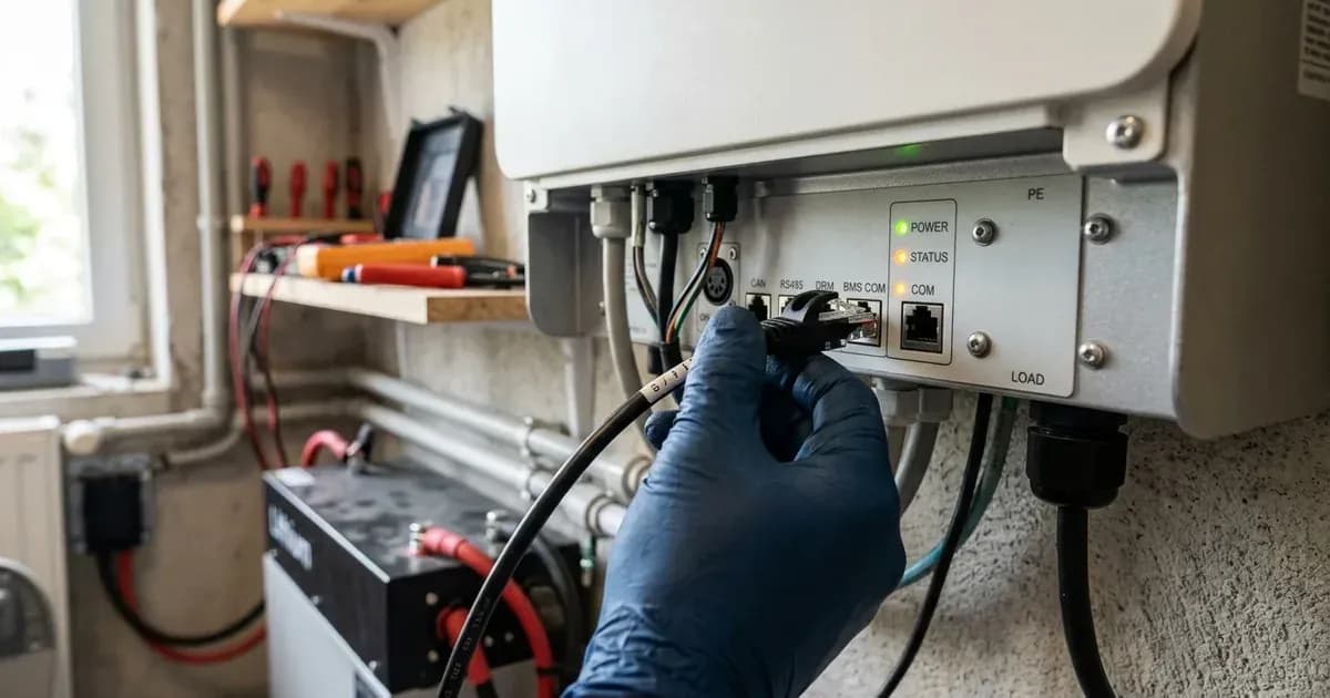
- Single Battery Setup: Connect the RJ45 cable from the Master battery COM1 port directly to the inverter BMS port. On a standalone module, COM1 and COM2 are functionally interchangeable.
- Parallel Multi Battery Bank: Connect inverter BMS port to Master COM1. Connect Master COM2 to Slave 1 COM1. Continue daisy chaining COM2 to COM1 across all units.
- Verify RJ45 Network Cable Pinout:
- Action: Check that your network cable strictly matches Livoltek's official pin definition:
- Pin 1 (Orange/White): BMS_CAN_H
- Pin 2 (Orange): BMS_CAN_L
- Pin 3 (Green/White): BMS_485_A
- Pin 4 (Blue): GND (Ground)
- Pin 5 (Blue/White): BMS_485_B
- Pins 6, 7, 8: NC (Not Connected)
- The Pylontech Cable Trap: Never use a standard Pylontech CAN cable. Livoltek and Pylontech BMS pin definitions differ, and the manual warns that the wrong wire sequence will cause failure. Always use the factory supplied cable from the Livoltek accessory box for a true pin-to-pin link. Note that while the battery exposes RS485 pins, Livoltek hybrid inverter manuals document CAN as the primary closed loop BMS link.
- Inspect Parallel Bank CAN Terminal Resistor:
- Action: Check the COM2 port on the very last slave module in your parallel bank of up to 5 units.
- Result: The supplied RJ45 CAN terminal resistor must be plugged into COM2 of the final battery.
- Meaning: Without this terminal resistor, high speed CAN bus data signals reflect across the bus, corrupting communication packets and triggering intermittent "BMS Lost" faults.
- Confirm Inverter Chemistry and Protocol Selection:
- Livoltek Hyper / HES Inverters: Set Battery Type to Li-Ion. The manual notes that setting Li-Ion without an active BMS cable triggers an immediate communication alarm by design. Approved batteries on Livoltek hybrids are Livoltek or Pylontech LV 40–60 V packs only.
- Growatt SPF Series: Set Program 05 to LI to run with a BMS link, then use Program 36 to select the protocol number (L01–L15 for RS485, L51–L65 for CAN, one at a time). Livoltek does not publish an Lxx protocol number for Growatt, so treat a CAN pairing as unconfirmed until your dealer supplies one. With type LI, Growatt cuts off output when communication fails. If communication cannot be established, switch Program 05 to User-Defined 2 and run in voltage mode (set Program 19/20 charge voltages equal for lithium and configure Program 21 low-DC cutoff).
- Deye Hybrid Inverters: Set Batt Mode to Lithium, then set Lithium Mode to the BMS protocol number from Deye's approved-battery document. We could not confirm that Livoltek appears in that list, so verify the protocol number with Deye or Livoltek support before relying on it. When linked, the inverter follows BMS voltage parameters (example: Shutdown 10%, Low Batt 20%, Restart 40%).
- Axpert Type Inverters (Inverex Veyron/VM Class): Select Program 05 as User-Defined since no Livoltek protocol exists. Configure Program 26 bulk (48 V default 56.4 V, range 48.0–61.0 V), Program 27 float (default 54.0 V), and Program 29 low DC cutoff (48 V default 42.0 V, range 42.0–48.0 V). Always stay inside Livoltek's operating voltage window of 40–58.4 V (all voltage setpoints are referenced to 25°C; charge only within 0–55°C for BLF-B51100 or 0–50°C for BLF51-5 IP65, as LFP cells cannot be charged below 0°C; community practice: bulk 56.0–57.6 V, float ~54 V).
- Execute the Deep Discharge Recovery (Emergency Charge):
- Action: If a Livoltek battery has remained uncharged for over 3 months, pack voltage may drop below the normal 40–58.4 V operating threshold, triggering a "Low battery" or "BAT Volt Fault" warning.
- Remedy: Use the Livoltek mobile application to activate the built-in Emergency Charge function. This charges the battery to 54 V and exits automatically after a 2 h period (referenced to 25°C; operating within the 0–55°C charging temperature range for BLF-B51100 or 0–50°C for BLF51-5 IP65; never charge below 0°C), restoring normal closed loop operation.
Livoltek Inverter Fault Resolution Matrix
Inverter platform | Fault shown / symptom | Root cause | Exact remedy |
|---|---|---|---|
Livoltek Hyper / HES | | CAN cable unplugged or wrong pinout | Check the battery type setting and the BMS cable — it must sit in COM1 and be wired to Pins 1/2 — then restart the inverter. |
Livoltek Hyper / HES | | Internal BMS communication failure | Perform a complete cold restart. If the error persists, escalate to an authorized dealer. |
Growatt SPF 3500/5000 ES | Output cut off with battery type set to LI | Battery BMS communication has failed | Recheck the BMS cable and the Program 36 protocol selection, or switch Program 05 to User-Defined 2 and run in voltage mode. |
Deye SUN-3.6/5/6K-SG03LP1 | No BMS link established in Lithium mode | Wrong protocol number, or Livoltek unconfirmed in Deye's approved-battery list | Check the cable against Livoltek's pin definition at the battery end and Deye's own BMS port mapping, then confirm the protocol number with Deye or Livoltek support. |
Parallel Bank Setup | Intermittent comm loss across slaves | Missing RJ45 terminal resistor | Insert the factory supplied RJ45 terminal resistor into COM2 of the last battery in the daisy chain. |
Parallel String Wiring and System Expansion Rules
When expanding Livoltek low-voltage battery storage banks:
- Maximum Module Limits: Official documentation permits paralleling up to 5 units in a single low-voltage bank.
- DC Isolator Sizing: A dedicated external two-pole DC circuit breaker rated at ≥125 A is mandatory between the battery bank and the inverter.
- Cable Gauge Sizing: Livoltek's Hyper manual calls for battery cable of at least 25 mm², because battery current exceeds 100 A. If you are wiring to a Growatt SPF instead, that manual specifies 35 mm² battery leads torqued to 2 Nm at the terminals. Kill power first and use insulated tools during terminal connection because a short circuit across a bank discharges hundreds of amperes.
For broader compatibility troubleshooting, review our guide on lithium battery inverter compatibility errors and our master inverter error code glossary.
Safety: Working with LiFePO4 Lithium Battery Systems
Observe these mandatory safety protocols when handling Livoltek lithium battery banks:
- Fire Safety Rules: Official Livoltek safety chapters explicitly state: extinguish a surrounding fire before it reaches the battery; if the battery itself has caught fire, do not try to extinguish the fire—evacuate people immediately.
- Submerged or Damaged Packs: Never access or power on a battery that has been submerged or physically damaged. Damaged packs are unfit for use; repack in original container and return to distributor.
- Electrolyte Exposure First Aid: If electrolyte contacts eyes, flush with flowing water for 15 minutes and seek medical attention; for skin contact, wash thoroughly with soap and water; if electrolyte is swallowed, seek immediate medical attention.
- Operating Temperatures: Charge only between 0–55°C (BLF-B51100 IP21) or 0–50°C (BLF51-5 IP65); LFP cells must never be charged below 0°C. Discharge temperature range is −20–55°C (IP21) or −10–55°C (IP65). Operating altitude must remain <4000 m with humidity between 5–95%.
- Handling and Isolation: Module weight is 44–55 kg per module, requiring a two-person lift (44–55 kg per module). Before performing maintenance, kill power, isolate the DC breaker, use insulated tools, and wait ≥10 min after power-off before touching terminals (a spanner or dropped tool across a bank shorts hundreds of amps).
- Disposal: All modules are WEEE-marked—never dispose of units in household garbage; professional recycling only.
When to call a technician instead
Contact a certified solar technician or an authorized Livoltek service center under the following conditions:
- The battery front panel Red LED remains continuously illuminated for more than 12 hours (note that red indicates a fault or SOC ≤ 8%).
- The battery displays a persistent "BAT Volt Fault" with voltage outside the permissible 40–58.4 V operating range (referenced to 25°C) and refuses to initiate Emergency Charge.
- Physical casing damage, liquid ingress, or burnt terminal connections are observed.
- Warranty claim processing: Livoltek provides a 5-year local warranty in Pakistan through authorized distributors (solarshop.livoltek.pk, buysolar.pk, kamalsolar.pk, etc.). Register your product serial number on the official Livoltek registration portal at livoltek.com/registration.html.
For professional escalation guidelines, consult our guide on when to call a solar technician and our parent diagnostic guide on solar battery not charging.
Figures as of August 2026.
Still showing the fault? Book a technician
If the steps above did not clear it, tell us the inverter or battery and the exact code. We pass it to a technician who covers your city; visit charges are quoted before they come.
How this pays for the site: the technician or verifier pays SolarNevs a fixed introduction fee. Nobody pays to be recommended, and you are free to use our free guides instead.
Frequently asked questions
What does 'BMS Lost' or 'BMS Fault' mean on a Livoltek hybrid inverter?
'BMS Lost' indicates the inverter has lost CAN communication with the battery BMS, while 'BMS Fault' indicates an internal BMS communication failure. The official Hyper manual instructs checking the battery type setting and the BMS cable connection, restarting the inverter, and escalating to dealer support if the fault repeats.
Can I use a Pylontech communication cable on a Livoltek battery?
No. Livoltek and Pylontech BMS pin definitions differ, and the Livoltek manual explicitly warns that a wrong wire sequence will cause failure. Livoltek requires pin-to-pin wiring for Pin 1 (BMS_CAN_H) and Pin 2 (BMS_CAN_L); always use the factory BMS cable supplied in the Livoltek accessory box.
What is the RJ45 pinout for Livoltek CAN communication?
The Livoltek BMS RJ45 pinout uses Pin 1 for BMS_CAN_H (orange/white), Pin 2 for BMS_CAN_L (orange), Pin 3 for BMS_485_A (green/white), Pin 4 for Ground (GND, blue), and Pin 5 for BMS_485_B (blue/white). Pins 6, 7, and 8 are not connected (NC). While the battery exposes RS485 pins, Livoltek hybrid inverter manuals document CAN as the primary closed loop BMS link.
Why is an RJ45 terminal resistor required in a Livoltek parallel bank?
When connecting up to 5 Livoltek units in parallel, communication is daisy chained from COM2 of each module to COM1 of the next. The supplied RJ45 CAN terminal resistor must be fitted into the COM2 port of the last battery in the bank to eliminate signal reflection and prevent communication errors.
How do I recover a Livoltek battery from deep discharge?
Livoltek hybrid inverters feature a built-in Emergency Charge function accessible via the mobile app, which charges a deeply depleted pack to 54 V and automatically exits after 2 h (all voltage setpoints are referenced to 25°C; charging permitted only within 0–55°C for BLF-B51100 or 0–50°C for BLF51-5 IP65; LFP cells must never be charged below 0°C). Livoltek manuals specify that batteries must not sit unused for more than 3 months without a recharge to prevent irreversible deep discharge.
References
- Livoltek BLF-B51100 User Manual PDF — accessed 23 August 2026
- Livoltek BLF51-5 IP65 User Manual PDF — accessed 23 August 2026
- Livoltek iPower HES User Manual PDF — accessed 23 August 2026
- Growatt SPF 3500/5000 ES User Manual — accessed 23 August 2026
- Deye SUN-3.6/5/6K-SG03LP1 User Manual PDF — accessed 23 August 2026
- SolarFeeds Livoltek Power Company Profile — accessed 23 August 2026
Related guides
More from inverter errors & fixes.