Victron BYD B-Box Installation Guide
Updated 16 September 2026 · By SolarNevs Research Desk, Dealer surveys + verified sources · 1 source · Method ↗
Key Takeaways
- Proper cable tightening is critical for safety and performance.
- CAN bus communication setup is essential for the Victron GX device to monitor the BYD battery.
- Always ensure a main system disconnection device is installed external to the battery cabinet.
- Stop work and consult a professional if screws seize or cables appear damaged during installation.
How do I install a BYD B-Box Res IP55 with a Victron MultiPlus system?
Installing a BYD B-Box Res IP55 battery with a Victron MultiPlus system involves careful physical connections and correct communication setup. The most common cause of issues is improper cable termination or incorrect CAN bus configuration.
Installation Steps
This section outlines the steps for physically installing and configuring the communication between your BYD B-Box Res IP55 battery and Victron MultiPlus system.
1. Physical Connections and Cable Management
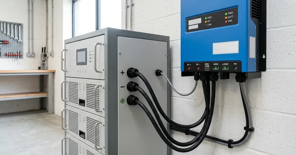
Begin by physically mounting the BYD B-Box Res IP55 battery, which typically consists of 4x2.5kWh battery modules, and the Victron MultiPlus inverter.
- Cable Tightening: Ensure all cables are seated and firmly tightened in the breaker blocks. Loose connections can lead to poor performance or safety hazards.
- Breaker Block Handling: When tightening screws in the breaker blocks, avoid overtightening. Overtightening can cause the breaker blocks to break.
- Cable Routing: Be aware of metal screws in cable management channels. It is commonly reported by installers that these metal screws could damage the single insulated battery cables. Route cables to prevent contact with sharp edges or screws.
- System Disconnection: Connect the output of the BYD main breaker to a main system disconnection device. This device, such as a DC breaker or fuse assembly, must be external to the battery cabinet.
- Emergency Shutdown: Ensure that any emergency shutdown mechanism for the system is very obvious and easily accessible. This is a community-reported best practice.
2. Communication Setup (CAN bus)
Proper communication between the BYD B-Box's Battery Management Unit (BMU) and the Victron GX device is essential for system operation and monitoring.
- BMU to GX Device Connection: Connect the BMU CAN bus RJ45 port on the BYD battery to a CAN bus port on your Victron Color Control GX (CCGX) or Venus GX device.
- GX Device CAN Ports: A CCGX typically has two CAN ports on one bus. For a Venus GX, the second CANbus is operational and configurable from the graphical user interface (GUI) in version 2.15 and later.
- Protocol Selection: The system uses CAN bus communication. You will need to configure the CAN bus protocol in your GX device settings. Options include "Victron CAN bus" and "BYD CAN bus." Ensure the correct protocol is selected for proper data exchange. The GX device will receive data from the battery modules via the BMU.
Common Installation Issues and Solutions
This table outlines common issues encountered during the installation of BYD B-Box batteries with Victron systems, along with their likely causes and fixes.
Symptom detail | Likely cause | Fix |
|---|---|---|
Loose cables in breaker blocks | Insufficient tightening of screws | Ensure cables are seated and firmly tightened in breaker blocks. |
Breaker block screws too tight | Overtightening during installation | Avoid overtightening to prevent breakage of the breaker blocks. |
Seized screw in access panel | Metal particles in threads | Clean threads. In severe cases, as commonly reported by installers, this may require cutting off and drilling out the seized screw. |
Damaged battery cables | Metal screws in cable management channels | Reroute cables to avoid contact with metal screws. Inspect cables for damage and replace if necessary. This is commonly reported by installers as a design concern. |
Safety: Critical Considerations During Installation
Working with high-voltage battery systems requires strict adherence to safety protocols to prevent injury and equipment damage.
- Cable Tightening: Always ensure cables are seated and firmly tightened in breaker blocks. Loose connections can generate heat and pose fire risks.
- Breaker Block Handling: Exercise caution when tightening breaker block screws. Overtightening can cause the blocks to break, potentially exposing live terminals.
- System Disconnection: A main system disconnection device (DC breaker or fuse assembly) must be installed external to the battery cabinet. This device provides a clear and obvious point to isolate the battery from the rest of the system during maintenance or emergencies.
- Emergency Shutdown: Ensure that an emergency shutdown procedure and mechanism are clearly marked and easily accessible. This is a community-reported safety best practice.
- Cable Management: Be mindful of metal screws in cable management channels. As commonly reported by installers, these can damage single insulated battery cables, leading to short circuits or ground faults. Inspect cable runs carefully.
When to call a technician instead
While many installation steps can be performed by a competent DIYer, certain situations warrant professional assistance. If you encounter any of the following, it is best to stop work and contact a qualified solar technician:
- Seized or Damaged Screws: If a screw seizes in a thread and cannot be removed or tightened properly, or if you need to cut off or drill out a screw, a technician has the specialized tools and experience to resolve this without further damage.
- Damaged Components: If any part of the battery, inverter, or wiring appears damaged, do not proceed with the installation. A technician can assess the damage and ensure safe operation.
- Unclear Wiring Diagrams: If you are uncertain about any wiring connections or the overall system layout, consult a professional. Incorrect wiring can lead to serious hazards and void warranties.
- Communication Failures: If, after following the communication setup steps, your Victron GX device does not properly detect or communicate with the BYD B-Box, a technician can diagnose and resolve complex communication issues.
- Safety Concerns: If at any point you feel unsafe or unsure about a procedure, prioritize your safety and seek expert help.
Frequently asked questions
What BYD B-Box model is covered in this guide?
This guide focuses on the BYD B-Box Res IP55, which typically includes 4x2.5kWh batteries. It is designed for use with Victron Energy's off-grid MultiPlus systems.
How do I connect the BYD B-Box to a Victron GX device?
Connect the BMU CAN bus RJ45 port on the BYD battery to a CAN bus port on your Victron Color Control GX (CCGX) or Venus GX device. The GX device will then receive data from the battery modules.
What are common installation issues with battery breaker blocks?
Common issues include screws that are too loose, leading to poor connections, or screws that are overtightened, which can cause the breaker blocks to break. Metal particles in the threads can also cause screws to seize.
What safety precautions are important during installation?
Ensure all cables are firmly tightened in their breaker blocks, but avoid overtightening. Always connect the output of the BYD main breaker to a main system disconnection device, such as a DC breaker or fuse assembly, located external to the battery cabinet.
What CAN bus protocols are used for Victron and BYD?
The system uses CAN bus communication. You will need to select the appropriate Victron CAN bus or BYD CAN bus protocol in your CCGX or Venus GX settings for proper communication.
References
- Victron Energy: BYD B-Box compatibility guide — accessed 23 August 2026
Related guides
More from sizing, net billing & installation.