Sunsynk CT Coil Wrong Readings: Troubleshooting Load and Export
Updated 16 September 2026 · By SolarNevs Research Desk, Dealer surveys + verified sources · 8 sources · Method ↗
Key Takeaways
- Incorrect load or export readings on your Sunsynk inverter often point to an issue with the CT (Current Transformer) coil installation.
- The first check for incorrect readings is the CT clamp's polarity and its placement on the incoming live supply.
- For three-phase systems, incorrect phase rotation can cause the load to appear to increase when the system is exporting power.
- Work involving the main incoming electrical supply and CT clamp installation requires a registered electrical person in South Africa, and a Certificate of Compliance (CoC).
Why Your Sunsynk Inverter Shows Wrong Load or Export
If your Sunsynk inverter displays load readings that do not make sense, shows export when there is none, or feeds power to the grid when it should not, the issue is often with the CT (Current Transformer) coil. The CT coil is crucial for the inverter to accurately measure the flow of electricity between your property and the grid. When it is incorrectly installed or configured, the inverter receives false data, leading to incorrect readings and behaviour.
How a CT Coil Works with Your Inverter
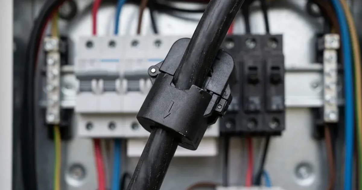
A CT coil is a device that measures the current flowing through a wire without making direct electrical contact. It clamps around the live incoming electrical cable to your property. As electricity flows through this cable, the CT coil senses the magnetic field created by the current and sends a proportional signal to your Sunsynk inverter.
The inverter uses this signal to understand how much power your property is importing from the grid or exporting to it. This information allows the inverter to manage your solar generation, battery charging, and grid interaction according to its programmed settings, such as zero export or selling first.
Common Sunsynk CT Coil Reading Problems and Solutions
Here are common issues with Sunsynk CT coils and how to address them:
Symptom | What it means | What to do |
|---|---|---|
Negative CT/HM reading on single-phase inverter | Incorrect CT clamp polarity. | Flip the CT clamp the other way around on the live incomer cable. |
Negative CT reading on inverter screen (DC switch OFF, 'use timer' disabled) | Polarity issue with the CT. | Change the clamp direction on the live incomer cable. |
Load increases when exporting (three-phase inverters) | Incorrect phase rotation (L1, L2, L3 not in correct order). | Use a clamp meter to read L1, L2, L3 and compare with the inverter display. Ensure PV is isolated and battery SOC is 100% for accurate grid readings. Correct the L1, L2, L3 connections. |
Grid-side load appears doubled | Incorrect wiring of extended CT clamp cable, specifically mixing solid colour cores with colour/white cores in CAT-6 cable. | Ensure solid colour cores are paralleled together and colour/white cores are paralleled together, not mixed. For extensions longer than 15 metres, consider using an external meter. |
No grid-side load readings | Incorrect CT placement, CT interference, incorrect CT connection, outdated firmware, incorrect system mode, or grid relay disconnection. | Ensure CT is on the live incomer before any connector (Henley) blocks or the DB, with at least 12 inches (30cm) clearance from other CTs. Check CT connections: white tail to pin 3, black tail to pin 4 for single-phase inverters. Ensure CT cables are not coiled or near AC/data cables. |
No export from system, export only at certain times, generation only matching load, generation dropping when batteries full, incorrect export figures | Various export settings issues or CT reading issues. | Check inverter settings: 'Solar Export' enabled, 'Export Power Limit' correct, 'Zero Export' mode not active, 'Max Solar Power' not too low, 'Grid Peak Shaving' threshold not too low. Test in 'Selling First' mode to isolate CT issues. |
Verifying Your CT Coil Installation
Accurate CT coil installation is critical for your Sunsynk inverter's performance.
CT Clamp Placement and Orientation
- Placement: The CT clamp must always be placed on the live incomer cable of your property. This means it should be positioned before any Henley blocks — the connector or splitter blocks ahead of the board — or the distribution board itself, so it measures the total power entering or leaving your premises.
- Clearance: If other CTs are nearby (e.g., for EV chargers or solar diverters), ensure they are placed at least 12 inches (30cm) apart to avoid interference.
- Cable Routing: CT cables should not be coiled and must be kept as far as possible from any other live cables or data cables, which can cause interference or block the signal.
Connecting the CT Coil to Your Inverter
The CT coil connects to specific pins on your Sunsynk inverter:
- Single-phase inverters: The white tail of the CT clamp should be connected to pin 3, and the black tail to pin 4.
- Three-phase inverters:
- Phase 1 CT tails connect to pin 3 and pin 4.
- Phase 2 CT tails connect to pin 5 and pin 6.
- Phase 3 CT tails connect to pin 7 and pin 8.
CT Ratio Settings
Your inverter needs to know the ratio of the CT coil to interpret its signal correctly.
- For standard Sunsynk CTs rated 100A / 50mA, the CT ratio is 2000:1.
- For High Voltage series inverters using 300A / 5A CTs, the CT ratio is 6000:1 (with a x100 multiplier). The CT ratio can be set in the inverter under 'Advanced Settings'.
CT Cable Length and Extension
Ideally, the cable length between the inverter and the CT clamp should be no more than 10 metres, though it can be extended up to 15 metres in some circumstances. If you need to extend the CT tails, the cable used must be made of copper and be of an equal or thicker gauge than the existing CT cables. If using CAT5/6 cable, a twisted pair should be used to reduce resistance and protect against interference. Mixing solid colour cores with colour/white cores in CAT-6 cable can cause interference, potentially doubling the perceived load.
When to Use an External Energy Meter
If you experience persistent issues with CT coil readings, or if the CT cable needs to be extended beyond 15 metres, an external energy meter can provide a more robust solution. Sunsynk inverters are compatible with several external meters, including models from Eastron and Owen Brothers.
Compatible External Meters
- Single-phase inverters: Eastron SDM120CT (120A / 40mA CT Coil), Eastron SDM230-Modbus, Owen Brothers OB115 Meter.
- Three-phase inverters: Eastron SDM630MCT, Eastron SDM630MCT v2, Eastron SDM630MCT-MV (these can also be configured for single-phase inverters).
Connecting an External Meter
External meters connect to the inverter via an RS485 connection.
- Wiring: Follow the specific wiring instructions for your chosen meter model. For example, an Eastron SDM120CT series meter typically wires Live into port 4 and Neutral into port 3, with the CT coil (black to port 2, white to port 1). RS485 wiring connects solid blue to RS485-B (port 9) and blue/white to RS485-A (port 10) on the meter side.
- Inverter Settings: Once connected, you must enable 'Ex_Meter_for_CT' in the inverter's 'Advanced Settings' and select the matching meter type in 'Meter Select'.
- Cable Length: An RS485 signal can be carried up to 1200 metres with specialist data cable, or up to 100 metres with Cat5/6 cable.
What You Can Check Yourself, and What You Cannot
You can safely check the inverter's display for negative readings, verify the CT clamp's visible direction, and check the inverter's settings for the CT ratio or external meter selection.
However, any work that involves physically interacting with the CT clamp on the main incoming electrical supply, connecting or disconnecting wires to the inverter's terminals, or working inside the inverter's enclosure, must be performed by a registered electrical person. In South Africa, such work requires a qualified installer and must be accompanied by a Certificate of Compliance (CoC) to ensure safety and adherence to electrical regulations. Attempting to work on live AC tails or the main supply without proper qualifications is extremely dangerous.
What the published sources do not tell you
While Sunsynk provides extensive guidance, there are some limitations in the publicly available documentation:
- CT Orientation Contradiction: Sunsynk's documentation contains conflicting advice on the CT clamp's arrow direction. One document states the arrow should point towards the inverter, while another states it should point away from the grid towards the inverter. In practice, verifying the reading (e.g., ensuring positive load readings) is more reliable than relying solely on the arrow.
- Detailed Three-Phase CT Verification: While issues like incorrect phase rotation are covered, a comprehensive step-by-step verification process for three-phase CTs, similar to the single-phase guide, is not explicitly detailed.
- Inverter Model-Specific Pin-out Configurations: While general pin-outs are provided, the documentation often refers to checking the specific inverter manual for exact pin configurations, which are not universally available in the provided support articles.
- Quantified CT Interference Impact: The documents mention interference can cause incorrect readings but do not quantify the potential error or provide specific diagnostic steps to confirm interference beyond physical separation.
Frequently asked questions
Why is my Sunsynk inverter showing negative load or export?
A negative reading for your CT or HM value on a single-phase inverter typically indicates incorrect CT clamp polarity. Flip the CT clamp the other way around on the live incomer cable to correct this.
Where should the Sunsynk CT clamp be placed?
The CT clamp should always be placed on the live incomer cable of your property. This must be before any Henley blocks or distribution boards to ensure it measures all incoming and outgoing grid power. Sunsynk writes for a British audience here: a Henley block is what a South African electrician would call a connector or splitter block ahead of the DB.
What does it mean if my three-phase Sunsynk inverter load increases when exporting?
If your three-phase inverter's load increases when exporting, it may be caused by incorrect phase rotation. Ensure the L1, L2, and L3 connections are in the correct order as per your inverter's requirements.
Can I extend the cable for my Sunsynk CT clamp?
Yes, you can extend the CT tails. The extension cable must be copper and of equal or thicker gauge. If using CAT5/6 cable, a twisted pair should be used to reduce resistance and protect against interference.
When should I consider using an external energy meter with my Sunsynk inverter?
An external energy meter like an Eastron SDM120CT can resolve persistent CT reading issues, especially if the CT clamp cable needs to be extended beyond 15 metres or if interference is a problem.
References
- Sunsynk Support: Single Phase Inverters - Checking the CT Coil is Reading Correctly — accessed 27 August 2026
- Sunsynk Support: CT Clamp Guide — accessed 27 August 2026
- Sunsynk Support: Three Phase Inverters - Load Increases When Exporting — accessed 27 August 2026
- Sunsynk Support: Grid-Side Load is Doubled — accessed 27 August 2026
- Sunsynk Support: No Grid-Side Load Readings — accessed 27 August 2026
- Sunsynk Support: Export Issues — accessed 27 August 2026
- Sunsynk Support: Eastron Meters - CT Selection and Settings — accessed 27 August 2026
- Sunsynk Support: Classic/Acure/Elite Single Phase Eastron Meter with Single Phase Inverter (SDM120CT Series) — accessed 27 August 2026
Related guides
More from inverter errors & fixes.