Troubleshooting Victron Pylontech Phantom US2000 CAN Bus Cable Issues
Updated 16 September 2026 · By SolarNevs Research Desk, Dealer surveys + verified sources · 1 source · Method ↗
Key Takeaways
- CAN-bus communication is critical for Victron-Pylontech systems to exchange vital data.
- Incorrect charge voltage settings can lead to slow charging or BMS-related issues.
- Pylontech batteries significantly restrict charging in cold temperatures.
- Always verify settings in your Victron GX device and VEConfigure software.
Why is my Victron system not communicating with my Pylontech US2000 batteries?
The most common cause for communication issues between a Victron system and Pylontech US2000 batteries is an incorrect or missing CAN-bus connection. You should first check the physical cable and then verify the communication status within your Victron GX device.
Diagnosis
Follow these steps to diagnose communication and charging issues with your Victron Pylontech system.
- Check CAN-bus connection:
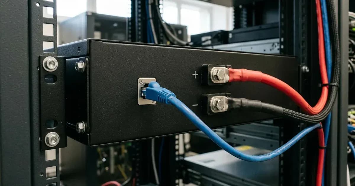
- What to do: Visually inspect the CAN-bus cable connecting your Pylontech battery bank to the Victron GX device (e.g., Cerbo GX). Ensure it is securely plugged into both ends.
- What it means: The CAN-bus connection is essential for the Victron GX device to receive the keep-alive signal, charge and discharge limits, error codes, and state of charge (SOC %) from the Pylontech BMS. Without this, the system cannot operate correctly.
- Verify GX device communication parameters:
- What to do: Access the parameters screen on your Victron GX device. Look for the 'charge current limit' (CCL) value.
- What it means: The CCL value displayed here is received from the Pylontech BMS via DVCC. If each Pylontech battery module is rated for 25A charge current, a displayed CCL of 75A indicates that three Pylontech battery modules are connected and communicating. An unexpected or zero CCL can indicate a communication problem.
- Inspect charge voltage settings:
- What to do: Check if DVCC (Distributed Voltage and Current Control) is enabled on your Victron system. Note the requested charge voltage from the battery and the actual capped voltage.
- What it means: When DVCC is enabled, the battery's BMS dictates the charge voltage. The Pylontech battery typically requests a charge voltage of 53.2V (at standard temperature). However, Victron systems often override this and cap the voltage at 52.4V (at standard temperature) to optimize battery life. Incorrect voltage settings can lead to suboptimal charging.
- Monitor charging behavior at high State of Charge (SoC):
- What to do: Observe the charging rate when your battery bank reaches the mid-90s percentage of its state of charge.
- What it means: Because the Victron system caps the battery voltage at 52.4V (at standard temperature), the state of charge will sometimes rise very slowly once it reaches the mid-90s. This is considered normal behavior and typically resolves over time as balancing occurs.
- Check ambient temperature:
- What to do: Note the ambient temperature around your Pylontech battery bank, especially during periods of limited charging.
- What it means: Pylontech's BMS restricts the Charge Current Limit of the battery in cold weather. Anecdotal reports suggest limitations begin below 18 degrees C, become severe below 10 degrees C, and charging is completely restricted below 2 degrees C.
- Review MPPT RS settings (if applicable):
- What to do: If you are using a Victron MPPT RS solar charge controller, check its Remote Mode setting in VictronConnect.
- What it means: For proper operation with Pylontech batteries, the Remote Mode in VictronConnect for an MPPT RS must be set to "Remote on/off", not "BMS".
- Observe current fluctuations during charging:
- What to do: Monitor the charge current after the battery has been charging for some time, especially with new batteries or after a deep discharge.
- What it means: After charging, the charge current often changes between 0A and 25A. This fluctuation is caused by cell balancing occurring inside the battery and is normal, particularly for new batteries or those that have experienced a deep discharge.
Cause/fix table
Symptom detail | Likely cause | Fix |
|---|---|---|
No communication / CAN-bus error | Incorrect or missing CAN-bus connection | Ensure the CAN-bus cable is securely connected between the Pylontech battery and the Victron GX device. |
Charge current limit (CCL) incorrect or zero | BMS not communicating module count or limits | Verify the CAN-bus connection. Check the 'charge current limit' in the GX device's parameters screen; it should reflect the total capacity of connected modules (e.g., 25A per module). |
Battery charging slowly at high SoC (mid-90s) | Victron system capping charge voltage | This is normal. The Victron system caps the charge voltage at 52.4V (at standard temperature), which can slow charging as the battery approaches 100% SoC. |
Battery not charging or charging very slowly in cold weather | Pylontech BMS restricting charge current due to low temperature | Ensure batteries are kept above 2 degrees C for full charging. Charging is limited below 18 degrees C and severely limited below 10 degrees C. |
MPPT RS not charging or showing errors | Incorrect Remote Mode setting | Set the Remote Mode in VictronConnect for the MPPT RS to "Remote on/off". |
Charge current fluctuating between 0A and 25A | Cell balancing in progress | This is normal behavior, especially for new batteries or after a deep discharge, as the BMS balances individual cells. |
Charge voltage higher than expected (e.g., 53.2V (at standard temperature)) | DVCC not enabled or voltage cap not applied | Ensure DVCC is enabled. The Victron system should cap the charge voltage at 52.4V (at standard temperature), even if the Pylontech BMS requests 53.2V (at standard temperature). |
Incorrect absorption or float voltage | Manual settings override or misconfiguration | Set absorption voltage to 52.0 V (at standard temperature) and float voltage to 51.0 V (at standard temperature) in VEConfigure. |
Settings for Victron Inverter/Chargers
For optimal performance and communication between your Victron inverter/charger and Pylontech US2000 batteries, specific settings are recommended.
- CAN-bus connection: It is essential to use the CAN-bus connection of the GX device (e.g., Cerbo GX). This connection communicates the keep-alive signal, charge and discharge limits, error codes, and state of charge (SOC %) between the batteries and the system.
- DVCC: Ensure DVCC is enabled. When DVCC is enabled, the battery (via the CAN-bms) is responsible for the charge voltage.
- Charge Voltage Cap: The Pylontech battery requests a charge voltage of 53.2V (at standard temperature). However, it is recommended to override the BMS and cap the voltage at 52.4V (at standard temperature) for improved longevity.
- Absorption Voltage: Set the absorption voltage to 52.0 V (at standard temperature) in VEConfigure.
- Float Voltage: Set the float voltage to 51.0 V (at standard temperature) in VEConfigure.
- MPPT RS Remote Mode: For MPPT RS controllers, the Remote Mode in VictronConnect must be set to "Remote on/off", not "BMS".
For more general information on battery types and their compatibility, you can refer to our guides on selecting the right battery for your solar system.
Safety: Lithium-ion Battery Handling
Pylontech US2000 batteries are lithium-ion. While generally safe, improper handling can lead to hazards.
- Thermal Events: Lithium-ion batteries can experience thermal runaway if overcharged, short-circuited, or physically damaged. Always adhere to specified charge and discharge limits.
- BMS Protection: The integrated Battery Management System (BMS) protects against overcharge, over-discharge, over-current, and over-temperature. Do not bypass or tamper with the BMS.
- Short Circuits: A short circuit across battery terminals can release high currents, leading to extreme heat, fire, or explosion. Always use insulated tools and ensure terminals are covered when not actively working on them. Disconnect all power sources (PV, AC, battery) before working on connections.
- Physical Damage: Avoid dropping, puncturing, or crushing the battery. Damaged batteries can be unstable and dangerous.
When to call a technician instead
While many troubleshooting steps can be performed by the user, some issues require professional intervention. If you have verified all connections and settings, and the problem persists, or if you encounter any physical damage to the battery or system components, it is time to call a qualified solar technician. Do not attempt repairs that involve opening the battery enclosure, as this can void warranties and pose significant safety risks.
Frequently asked questions
Why is my Pylontech battery charging slowly at high SoC with Victron?
The Victron system caps the charge voltage at 52.4V (at standard temperature) for Pylontech batteries. This can cause the state of charge to rise slowly once it reaches the mid-90s, which is normal behavior.
What is the correct charge voltage for Pylontech batteries with Victron?
While the Pylontech BMS requests a specific voltage, Victron systems typically cap the charge voltage slightly lower (e.g., at 52.4V (at standard temperature) at 25 degrees C).
Why is my Pylontech battery not charging in cold weather?
Pylontech's BMS restricts the charge current limit in cold temperatures. Charging may be limited below 18 degrees C, severely limited below 10 degrees C, and completely restricted below 2 degrees C.
How do I check the number of Pylontech modules connected to Victron?
You can check the 'charge current limit' (CCL) displayed in the Victron GX device's parameters screen. If each battery is rated for 25A charge current, dividing the displayed CCL by 25A indicates the number of connected modules.
What is the purpose of the CAN-bus connection between Victron and Pylontech?
The CAN-bus connection is essential for communication between the Victron GX device and the Pylontech BMS. It transmits the keep-alive signal, charge and discharge limits, error codes, and the state of charge (SOC %).
References
- Victron Energy Pylontech Phantom Compatibility — accessed 23 August 2026
Related guides
More from inverter errors & fixes.