Victron Hub-4 External Control Loop: Modes 2 & 3 Explained
Updated 16 September 2026 · By SolarNevs Research Desk, Dealer surveys + verified sources · 1 source · Method ↗
Key Takeaways
- Victron Hub-4 external control allows integration of Multi/Quattro inverters with custom control systems.
- Modes 2 and 3 offer different levels of control, from grid power setpoints to direct device commands.
- Modbus-TCP via a CCGX is a common and accessible method for external control implementation.
- Direct VE.Bus RS485 control via an MK2 device is possible but requires advanced protocol understanding.
What is Victron Hub-4 External Control?
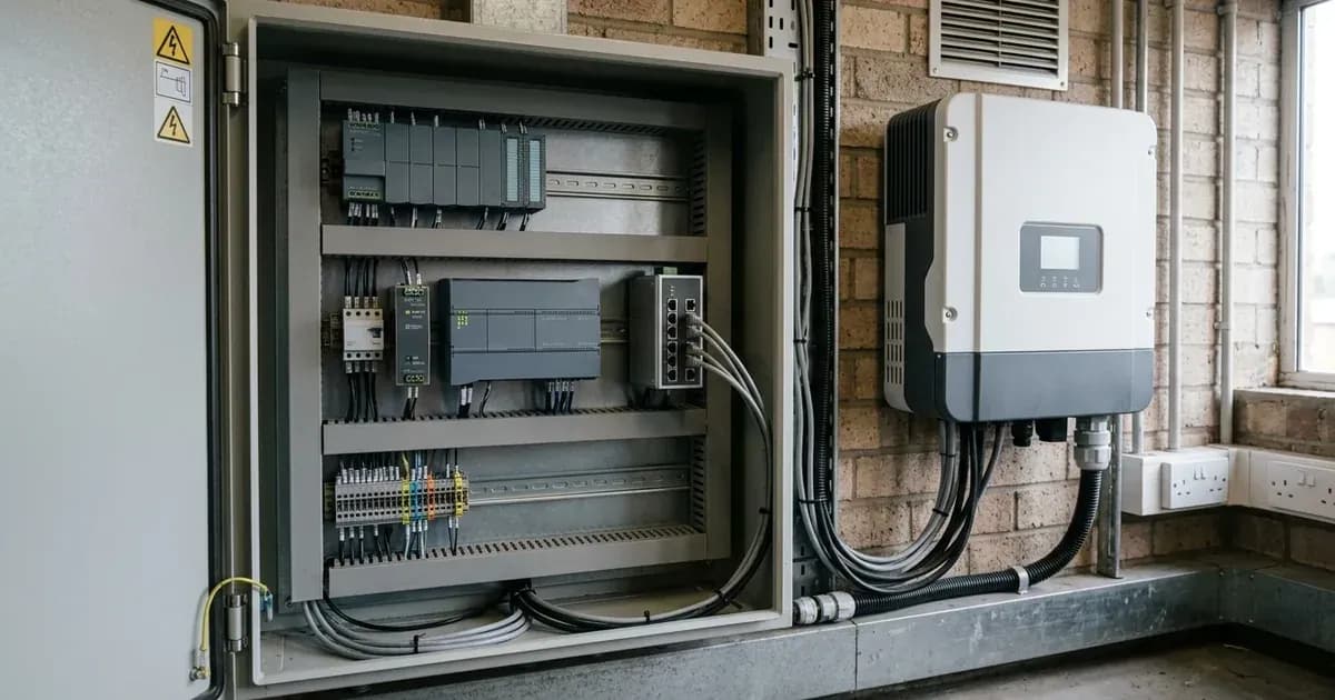
Victron Hub-4 external control provides a framework for integrating Victron Multi or Quattro inverter/chargers into custom-designed systems, such as those managed by a PLC. This allows an external control module to dictate how the inverter operates in a grid-parallel setup, managing power flow to and from the grid. The goal is to enable precise, automated control over the inverter's behavior, adapting to specific system requirements.
Implementing Hub-4 External Control: Key Methods
There are several ways to implement external control for Victron Hub-4 modes, each offering different levels of complexity and functionality. The primary methods involve using a Victron CCGX (Color Control GX or similar GX device) with Modbus-TCP, running scripts directly on the CCGX, or a direct connection via an MK2 device to the VE.Bus RS485.
1. Modbus-TCP Control via CCGX
This is a common method where an external control module, such as a PLC, sends commands to the CCGX using Modbus-TCP. The CCGX then translates these commands for the connected Multi or Quattro inverter/charger. This approach leverages the CCGX's network capabilities and simplifies the interface for the external system.
2. Self-Implemented Scripts on CCGX
For systems where adding an external PLC is not desired, scripts can be run directly on the CCGX. These scripts can achieve the same control functionality as an external module, using the CCGX's internal processing capabilities to manage the inverter's behavior based on custom logic.
3. Direct VE.Bus RS485 Control via MK2
It is possible to bypass the CCGX entirely and connect directly to the VE.Bus RS485 using an MK2-RS232 or MK2-USB device. This method offers direct control over the inverter. However, it is important to note that the MK2 protocol is not an easy protocol to work with, requiring a deep understanding of Victron's communication standards.
Hub-4 Mode 2: Advanced Control Points
Hub-4 Mode 2 provides specific Modbus-TCP registers for advanced control over grid interaction and battery management. These settings allow an external system to finely tune the inverter's behavior.
Setting Name | Values | Protocol |
|---|---|---|
Grid power setpoint | Positive: take power from grid. Negative: send power to grid. Default: 0W. | Modbus-TCP register 2700 |
Max charge current (fractional) | 0%: disable charging. 100%: unlimited charging. >0% and <100%: reduces charge current. | Modbus-TCP register 2701 |
Max discharge current (fractional) | 0%: disable discharging. 100%: unlimited discharging. >0% and <100%: reduces discharge current. | Modbus-TCP register 2702 |
The Grid power setpoint (Modbus-TCP register 2700) allows you to specify the exact power in Watts that the Multi or Quattro should draw from or feed into the grid. A positive value means the inverter draws power from the grid, while a negative value means it feeds power into the grid. The default setting is 0W, indicating no active grid power exchange.
The Max charge current (fractional) (Modbus-TCP register 2701) enables control over the battery charging process. Setting it to 0% disables charging, while 100% allows unlimited charging. Values between 0% and 100% can be used to reduce the charge current, useful for managing battery health or grid load.
Similarly, the Max discharge current (fractional) (Modbus-TCP register 2702) controls battery discharging. A 0% value disables discharging, and 100% allows unlimited discharging. Intermediate values can limit the discharge current, which can be important for battery longevity or managing system output.
Hub-4 Mode 3: Custom Control Points
Hub-4 Mode 3 offers more direct and granular control over the inverter's operational state and power output. This mode is suitable for systems requiring immediate and precise command execution.
Setting Name | Values | Protocol |
|---|---|---|
Switch | on, charger-only, inverter-only, off | External control loop |
Power setpoint in Watts | Regulates power on AC-input. | External control loop |
Disable charge flag | Boolean | External control loop |
Disable feedback flag | Boolean | External control loop |
The Switch control allows you to set the operational mode of the inverter/charger to on, charger-only, inverter-only, or off. This provides fundamental control over the device's primary functions.
The Power setpoint in Watts directly regulates the power on the AC-input. This allows for precise control over the amount of power the inverter draws or supplies to the AC load or grid connection.
Boolean flags like Disable charge flag and Disable feedback flag offer simple on/off controls for specific functions, providing quick ways to modify the inverter's behavior.
Hub-4 Mode 3 - MK2 Direct Control
For advanced users, Hub-4 Mode 3 can also be implemented via direct VE.Bus RS485 communication using an MK2 device. This method accesses specific RAM IDs for control.
Setting Name | Values | Protocol |
|---|---|---|
Setpoint in Watts | Signed integer (2's complement for negative values) | VE.Bus RS485 via MK2, RAM ID 129 (AssistantRAM0) |
Disable charge flag | bit0 of AssistantRAM1 | VE.Bus RS485 via MK2, RAM ID 130 (AssistantRAM1) |
Disable feedback flag | bit1 of AssistantRAM1 | VE.Bus RS485 via MK2, RAM ID 130 (AssistantRAM1) |
The Setpoint in Watts is controlled via AssistantRAM0 (RAM ID 129), using a signed integer where negative values are represented by 2's complement. This allows for direct power regulation.
The Disable charge flag is located at bit0 of AssistantRAM1 (RAM ID 130), and the Disable feedback flag is at bit1 of AssistantRAM1. These bit-level controls offer very low-level access to the inverter's functions.
Safety
When working with Victron Multi or Quattro inverter/chargers, always prioritize electrical safety. These devices handle significant power and voltage. Before performing any connections or modifications, ensure that all AC and DC power sources, including PV and battery inputs, are completely isolated. Use insulated tools and follow all local electrical codes. A spanner across a battery bank can short hundreds of amps, causing severe burns or equipment damage. The provided documentation does not detail specific safety guidelines for implementing external control loops, so general electrical safety practices are paramount.
When to call a technician instead
Implementing Hub-4 external control, especially using direct MK2 protocol communication, requires a strong understanding of power electronics, communication protocols, and programming. The MK2 protocol is noted as not being an easy protocol. If you are unsure about any steps, encounter unexpected behavior, or lack the necessary technical expertise, it is advisable to consult a qualified solar or electrical technician. Incorrect implementation can lead to system instability, damage to equipment, or safety hazards.
Frequently asked questions
What is Victron Hub-4 external control?
Victron Hub-4 external control allows an external system, such as a PLC, to manage Victron Multi or Quattro inverter/chargers operating parallel to the grid. It enables custom control over grid power flow and battery charging/discharging.
Which Victron devices support Hub-4 external control?
The Victron Multi and Quattro bidirectional inverter/chargers support Hub-4 external control. These devices can be integrated into a customer-designed system for grid-parallel operation.
How do Hub-4 Mode 2 and Mode 3 differ?
Hub-4 Mode 2 provides advanced control points like grid power setpoint and fractional charge/discharge currents, typically via Modbus-TCP. Hub-4 Mode 3 offers more direct control over functions like switching the inverter on/off or setting a specific power in Watts.
What communication protocols are used for Hub-4 external control?
Hub-4 external control primarily uses Modbus-TCP via a CCGX for Modes 2 and 3, or direct VE.Bus RS485 communication via an MK2 device for Mode 3. Modbus-TCP is generally simpler to implement for external systems.
Can I control the system without a Victron CCGX?
Yes, it is possible to implement Hub-4 Mode 3 control without a CCGX by using an MK2-RS232 or MK2-USB device for direct connection to the VE.Bus RS485. However, the MK2 protocol is noted as not being an easy protocol to work with.
References
- Victron Energy System Integration: Hub4 Grid Parallel External Control Loop — accessed 23 August 2026
Related guides
More from sizing, net billing & installation.