Victron VE.Bus Parallel and Three-Phase System Setup Guide
Updated 16 September 2026 · By SolarNevs Research Desk, Dealer surveys + verified sources · 1 source · Method ↗
Key Takeaways
- Parallel and three-phase Victron VE.Bus systems are complex and require specific configuration and wiring.
- All units in a system must be of the same type, have the same firmware version, and compatible Compatibility IDs.
- Symmetrical wiring for both DC and AC connections is critical for stable operation and proper load sharing.
- Incorrect phase rotation will prevent mains input acceptance and must be corrected by wiring changes or reprogramming.
My Victron VE.Bus system is not accepting mains input or showing incorrect data. What should I check?
If your Victron VE.Bus system does not accept mains input and operates only in inverter mode, the most common cause is an incorrect phase rotation in the AC wiring. If you observe incorrect or missing data on your GX device or VRM portal, or if input current limits are not working properly, this can indicate a non-symmetrical installation combined with unsupported monitoring.
Diagnosis Steps for VE.Bus Parallel and Three-Phase Issues
Follow these steps to diagnose common issues with Victron VE.Bus parallel and three-phase systems.
- Verify Unit Compatibility and Firmware:
- Check: Ensure all units in your system are the same model type (e.g., all 15kVA Quattros).
- Result: If units are different types, the system will not function correctly in parallel or three-phase.
- Check: Confirm all units have the same firmware version.
- Result: If firmware versions differ, update all units to the latest version during commissioning.
- Check: Locate the 4-digit Compatibility ID on the sticker of each unit. If no sticker, the ID is the first 4 digits of the complete firmware number followed by 'A'. For firmware 2699xxx without a sticker, the ID is 2629_A.
- Result: All units in the VE.Bus system must have an identical 4-digit number in their Compatibility ID. Units in a single phase (parallel units) must also have an identical letter in their Compatibility ID.
- Inspect AC Wiring for Phase Rotation:
- Check: Observe if the system is accepting mains input.
- Result: If the system operates only in inverter mode and does not accept mains, it indicates a phase rotation issue.
- Action: If a "Phase Rotation Alarm" is present, the mains input is not accepted due to incorrect phase rotation.
- Examine Wiring Symmetries and Connections:
- Check: Verify that the DC wiring connects every DC connection (on every Multi/Quattro and on every battery) together to a single DC bus.
- Result: Building systems with separated batteries on multiple (separated) DC bus structures connected to subsets of the Multi/Quattro units in the cluster will not work.
- Check: For parallel and three-phase setups, ensure both the DC and AC wiring are symmetrical per phase. This means using the same length, type, and cross-section of cable to every unit in the phase.
- Result: Non-symmetrical wiring can lead to uneven load sharing and system instability.
- Check: Confirm that each unit is fused individually on both AC and DC sides.
- Result: Use the same type of fuse on each unit due to the need for consistent resistance.
- Review System Monitoring Setup:
- Check: If you are using a GX device (like a Cerbo) or the VE.Bus Smart Dongle for monitoring.
- Result: If your installation is non-symmetrical (e.g., different numbers of units per phase), combining it with a GX device or VE.Bus Smart Dongle is not supported. Numbers and information shown on the GX device as well as VRM portal will or can be wrong, and controlling the system, for example setting input current limits, will not always work properly either.
Cause and Fix Table for VE.Bus System Issues
Symptom detail | Likely cause | Fix |
|---|---|---|
System does not accept mains input, operates only in inverter mode | Mains input wired with incorrect phase rotation compared to unit programming | Swap two phases in the AC wiring to correct the rotation, or re-program the units to match the existing wiring rotation. |
Incorrect or missing data on GX device/VRM portal, input current limits not working properly | Non-symmetrical installation (e.g., different number of units per phase) combined with a GX device or VE.Bus Smart Dongle monitoring | Reconfigure the system to be symmetrical (same number of units per phase) or use only a Digital Multi Control without other monitoring devices. |
"Phase Rotation Alarm" displayed | Mains input not accepted due to incorrect phase rotation | Swap two phases in the AC wiring to correct the rotation, or re-program the units to match the existing wiring rotation. |
Uneven load sharing, system instability, or unexpected shutdowns | Non-symmetrical DC or AC wiring to units in parallel or three-phase | Ensure both DC and AC wiring are symmetrical per phase: use the same length, type, and cross-section of cable to every unit in the phase. |
Units not communicating or system not forming a cluster | Mismatched firmware versions or Compatibility IDs among units | Update all units to the latest identical firmware version. Ensure all units have an identical 4-digit number in their Compatibility ID, and parallel units have an identical letter. |
MultiPlus-II 8k, 10k, 15k units not operating correctly in parallel | Missing external AC transfer switch | Install an external AC transfer switch as required for these specific MultiPlus-II models in parallel configurations. |
System fails to operate with multiple battery banks | Multiple separated DC bus structures connected to subsets of Multi/Quattro units | Connect every DC connection (on every Multi/Quattro and on every battery) together to a single DC bus. |
Configuring Victron VE.Bus for Parallel and Three-Phase Operation
Setting up Victron VE.Bus inverters for parallel or three-phase operation requires careful attention to compatibility, firmware, and wiring.
Unit Compatibility and Firmware
All units intended for a parallel or three-phase system must be of the same type. For example, 15kVA Quattro units can be configured with up to 5 units in parallel for single-phase operation, supporting a 75kVA system. For three-phase, up to 4 units per phase can be used, totaling 12 units for a 180kVA system. Similarly, 10kVA Quattro units support up to 6 units in parallel for single-phase (60kVA) or 5 units per phase in a three-phase setup (15 units total, 150kVA).
It is essential that all units in one system have the same firmware version. Always update all units to the latest firmware version during commissioning of the system.
Compatibility ID
The Compatibility ID ensures units can communicate correctly. This ID can be found on the stickers of the units. If there is no compatibility ID on the sticker, the compatibility ID consists of the first 4 digits of the complete firmware number followed by the letter A. For units with firmware 2699xxx and no sticker, the compatibility ID is 2629_A.
- System-wide: Make sure that the 4-digit number in the compatibility ID of all units in the VE.Bus system is identical.
- Per-phase: Make sure that units in a single phase (so parallel units) have an identical letter in the compatibility ID.
Wiring Requirements
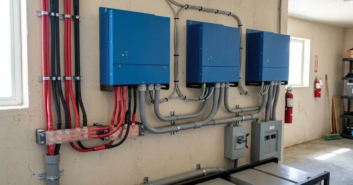
Both DC and AC wiring need to be symmetrical per phase. Use the same length, type, and cross-section of cable to every unit in the phase. This ensures balanced current flow and prevents issues.
- DC Wiring: Every DC connection (on every Multi/Quattro and on every battery) has to be connected together to a single DC bus. Do not build systems with separated batteries on multiple (separated) DC bus structures connected to subsets of the Multi/Quattro units in the cluster, as this will not work.
- AC Fusing: Each unit needs to be fused individually. Make sure to use the same type of fuse on each unit due to the need for consistent resistance.
- DC Fusing: Each unit needs to be fused individually. Make sure to use the same type of fuse on each unit due to the need for consistent resistance.
- AC Cabling: Do not over-dimension the AC cabling. Using extra thick cabling has negative side effects, though specific details are not provided.
- MultiPlus-II Specifics: MultiPlus-II 8k, 10k, and 15k models require an external AC transfer switch for parallel connection.
Symmetrical Installation for Three-Phase Systems
For three-phase systems, a symmetrical installation is required. The same number of units need to be installed on each phase.
Safety: Working with Complex VE.Bus Systems
Parallel and multiphase systems are complex. We do not support or recommend that untrained and/or inexperienced installers work on these size systems.
- Training: Victron is able to provide specific training for these systems to distributors via their regional sales manager. There is advanced training theory and practical videos and competency exams for 3 phase and parallel installation and commissioning available on Victron Professional -> Online Training.
- Installer Experience: It is recommended to hire an installer that has experience with these more complex Victron systems, for both the design and the commissioning.
- Electrical Safety: Always isolate PV, battery, and AC breakers before working on the system. Wait for the manual's specified capacitor-discharge time before opening any unit. Opening the unit is authorized-service work.
- Wiring: Ensure all wiring is correctly sized, terminated, and fused. Incorrect wiring can lead to fire hazards or equipment damage.
When to call a technician instead
Given the complexity of Victron VE.Bus parallel and three-phase systems, it is often best to consult a qualified and experienced installer. If you are unsure about any step in the configuration, wiring, or troubleshooting process, or if the system displays persistent errors after basic checks, contact a professional. Attempting to configure or repair these systems without proper training and tools can lead to equipment damage, system failure, or safety hazards. Victron Energy strongly recommends hiring an installer with experience in these complex systems for both design and commissioning.
Frequently asked questions
What Victron VE.Bus models can be used in parallel or three-phase configurations?
Victron MultiPlus and Quattro models are designed for parallel and three-phase systems. For example, 15kVA Quattro units can be configured with up to 5 units in parallel for single-phase, or up to 4 units per phase in a three-phase system, totaling 12 units for 180kVA.
What is the maximum number of Victron Quattro 10kVA units in a three-phase system?
A maximum of 15 Victron Quattro 10kVA units can be used in a three-phase system, with up to 5 units per phase. This configuration supports a total system size of 150kVA.
What is a 'Phase Rotation Alarm' in a Victron VE.Bus system?
A Phase Rotation Alarm indicates that the mains input is not accepted because the phase rotation is incorrect. To fix this, you must swap two phases in the wiring or re-program the units to match the desired wiring rotation.
Why is symmetrical wiring important for Victron VE.Bus parallel and three-phase systems?
Symmetrical wiring ensures that all units in a phase receive power evenly. Both DC and AC wiring must be symmetrical per phase, meaning the same length, type, and cross-section of cable should be used for every unit within that phase.
What is the Compatibility ID and why is it important for Victron VE.Bus systems?
The Compatibility ID is a 4-digit number and letter found on the unit's sticker or derived from its firmware. All units in a VE.Bus system must have an identical 4-digit number in their Compatibility ID, and units in a single phase (parallel units) must also have an identical letter in their Compatibility ID to ensure proper communication and operation.
References
- Victron Energy VE.Bus Manual: Parallel and Three-Phase Systems — accessed 23 August 2026
Related guides
More from sizing, net billing & installation.