Victron GX SolarEdge Modbus TCP Setup: Troubleshooting Connection Issues
Updated 17 September 2026 · By SolarNevs Research Desk, Dealer surveys + verified sources · 1 source · Method ↗
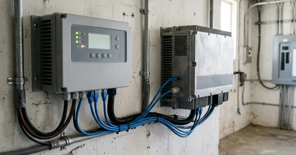
Key Takeaways
- Incorrect firmware versions or configuration settings are the most common causes of integration issues.
- Always begin by verifying the firmware version of your SolarEdge inverter against the minimum requirements.
- Working with electrical systems carries risks; always isolate power before making physical connections.
- If frequency shifting or backend parameters require adjustment, contact SolarEdge support directly.
Why is my Victron GX not detecting my SolarEdge inverter via Modbus TCP?
The most common reasons for a Victron GX device failing to detect a SolarEdge inverter via Modbus TCP involve incorrect firmware, misconfigured communication settings, or network issues. The first step is to confirm that your SolarEdge inverter meets the minimum firmware requirements for integration.
Diagnosis
Follow these steps to diagnose and resolve common communication problems between your Victron GX device and SolarEdge inverter.
- Check SolarEdge Inverter Firmware Version:
- Observable Check: Access your SolarEdge inverter's interface (SetApp or LCD display) and locate its current firmware version.
- What it means: If your inverter is a SetApp model, it requires "Firmware 4.8.24 or higher". For LCD models, "Firmware 3.25xx or higher" is necessary. If the firmware is older, update it to the specified version or newer.
- Verify Alternative Power Source (APS) Mode Configuration:
- Observable Check: Navigate through your SolarEdge inverter's settings.
- For SetApp inverters: Look for "Commissioning -> Communication -> GPIO -> Power Reduction Interface (RRCR) Mode -> Alternative Power Source."
- For LCD inverters: Look for "Communication -> GPIO Conf -> Device Type -> Alternative Power Src."
- What it means: This setting must be enabled for the Victron GX to control the SolarEdge inverter's output via frequency shifting. This "APS feature is only available for 3phase and 1phase HDwave inverters." If you have multiple SolarEdge inverters, "Alternative Power Source mode should be configured on the master inverter. Once configured, the master inverter automatically sets all detected slave inverters to Alternative Power Source mode." Only the Leader SolarEdge inverter requires the GPIO setting to Alternative Power Source configuration.
- Confirm Modbus TCP Port and SunSpec Settings:
- Observable Check: In your SolarEdge inverter's communication settings, check the Modbus TCP port and SunSpec configuration.
- What it means: The Modbus TCP port should be "Edit port to 502". The SunSpec protocol should be set to "SunSpec (Non-SE Logger)" for SetApp inverters or "Non-SE Logger" for LCD inverters. The SunSpec Device ID must be "Edit to 126". Ensure these values are exact. If you have multiple inverters, "Each inverter requires its own TCP connection and IP address with the same SunSpec setting for each inverter."
- Inspect Network Connectivity:
- Observable Check: Verify that both your Victron GX Device and the SolarEdge system are connected to the same local area network (LAN) or WiFi network. Check the IP address of the SolarEdge inverter.
- What it means: Proper network communication is essential. "Ensure that the GX Device and the SolarEdge system are both on the same LAN or WiFi network." It is also advised to set the SolarEdge inverter’s IP address to a static IP by disabling DHCP. After setting a static IP, search for the IP address on your GX Device.
- Check Zero-Feed-In Requirements (if applicable):
- Observable Check: If you are implementing zero-feed-in, confirm the presence of a "SolarEdge grid meter (required for Zero feedback)" and a "Dry-contact for sensing the grid supply."
- What it means: For zero-feed-in functionality, these components are critical. The dry contact should be connected using "twisted pair wires from the dry contact terminals to the L1 and V terminals of the Communication Board inside the inverter". If multiple inverters are present, "Only the Leader SolarEdge inverter requires the dry-relay contact connection."
- Review Frequency Shifting Parameters:
- Observable Check: Check the P(f) settings in your SolarEdge inverter.
- What it means: For proper ESS assistance, the SolarEdge inverter's P(f) settings should be "50.2Hz, 100% Power" for P0 and "51.2Hz, 0% Power" for P1. The Victron ESS system expects the solar converter to "start reducing its output power at 50.2Hz" and for "Output power will be reduced to a minimum when the frequency is 51.2Hz". The converter "will disconnect when the frequency is higher than 51.5Hz". If these are not configured, the inverter will not respond to frequency changes from the Victron system. For multiple inverters, "Setup the frequency shifting bandwidth for all the SolarEdge inverters on site."
Cause/fix table section
Symptom detail | Likely cause | Fix |
|---|---|---|
Victron GX does not detect SolarEdge inverter | Incorrect firmware version on SolarEdge inverter | Update SolarEdge SetApp inverter to "Firmware 4.8.24 or higher" or LCD inverter to "Firmware 3.25xx or higher". |
Inverter not responding to Victron GX control | Alternative Power Source (APS) mode not enabled | Enable APS mode: SetApp: "Commissioning -> Communication -> GPIO -> Power Reduction Interface (RRCR) Mode -> Alternative Power Source." LCD: "Communication -> GPIO Conf -> Device Type -> Alternative Power Src." |
Communication error via Modbus TCP | Incorrect Modbus TCP port or SunSpec settings | Set Modbus TCP port to "502". Set SunSpec protocol to "SunSpec (Non-SE Logger)" (SetApp) or "Non-SE Logger" (LCD). Set SunSpec Device ID to "126". |
Inverter not visible on Victron GX network scan | GX Device and SolarEdge on different networks or DHCP issues | Ensure "the GX Device and the SolarEdge system are both on the same LAN or WiFi network." Set SolarEdge inverter to a static IP address. |
Zero-feed-in not functioning | Missing grid meter or dry-contact wiring | Install "SolarEdge grid meter (required for Zero feedback)" and "Dry-contact for sensing the grid supply." Connect "twisted pair wires from the dry contact terminals to the L1 and V terminals of the Communication Board inside the inverter". |
SolarEdge inverter not reducing power output with high frequency | Incorrect P(f) settings or backend parameter | Configure P(f) P0 to "50.2Hz, 100% Power" and P1 to "51.2Hz, 0% Power". Contact SolarEdge Support to change the backend parameter for frequency shifting. |
Multiple SolarEdge inverters not integrating correctly | Incorrect RS485-1 interconnection or individual TCP settings | Interconnect inverters via RS485-1 (Leader/follower). "Each inverter requires its own TCP connection and IP address with the same SunSpec setting for each inverter." "Enable Grid Control for all the SolarEdge inverters on site." |
Communication and Pairing Settings
Successful integration between a Victron GX device and a SolarEdge inverter relies on precise communication and pairing settings. The primary protocol used for this integration is Modbus TCP with SunSpec.
- Firmware Requirements:
- SolarEdge SetApp inverters require "Firmware 4.8.24 or higher".
- SolarEdge LCD inverters require "Firmware 3.25xx or higher".
- These versions enable the necessary Alternative Power Source (APS) mode.
- Alternative Power Source (APS) Mode:
- This mode allows the SolarEdge inverter to respond to frequency shifting commands from the Victron GX device, which is crucial for AC-coupled systems and zero-feed-in.
- For SetApp inverters, configure this via "Commissioning -> Communication -> GPIO -> Power Reduction Interface (RRCR) Mode -> Alternative Power Source."
- For LCD inverters, set it via "Communication -> GPIO Conf -> Device Type -> Alternative Power Src."
- This feature is specifically available for "3phase and 1phase HDwave inverters." If you have multiple inverters, "Alternative Power Source mode should be configured on the master inverter."
- Modbus TCP and SunSpec Configuration:
- The Modbus TCP port on the SolarEdge inverter must be set to "502".
- The SunSpec protocol should be selected as "SunSpec (Non-SE Logger)" for SetApp models or "Non-SE Logger" for LCD models.
- The SunSpec Device ID must be "126".
- For multiple inverters, "Each inverter requires its own TCP connection and IP address with the same SunSpec setting for each inverter."
- Network Setup:
- Both the Victron GX device and the SolarEdge inverter must reside "on the same LAN or WiFi network."
- It is recommended to assign a static IP address to the SolarEdge inverter by disabling DHCP on the inverter's network settings.
- Frequency Shifting Parameters (ESS Assistance):
- The SolarEdge inverter's P(f) settings dictate its power response to grid frequency changes.
- P0 should be "50.2Hz, 100% Power".
- P1 should be "51.2Hz, 0% Power".
- These settings ensure that the "solar converter will start reducing its output power at 50.2Hz" and "Output power will be reduced to a minimum when the frequency is 51.2Hz". The inverter "will disconnect when the frequency is higher than 51.5Hz".
- A critical step is to "contact SolarEdge Support to change a parameter in the backend to allow the frequency shifting with APS mode." This backend parameter change is necessary for the frequency shifting to function correctly.
- Multiple Inverter Integration:
- SolarEdge inverters in a multi-inverter setup need to be "interconnected via RS485-1, with a Leader, follower configuration."
- "Enable Grid Control for all the SolarEdge inverters on site" under Power control -> Grid Control -> Enable.
- Only the Leader SolarEdge inverter requires the physical dry-relay contact connection and the GPIO setting to Alternative Power Source configuration.
Safety: Working with Inverter Systems
Always prioritize safety when working with electrical systems. Inverter installations involve high voltages and currents that can be hazardous.
- Isolate Power: Before performing any physical wiring or making connections, ensure all power sources to the inverter and the Victron GX device are disconnected. This includes AC grid power, PV array input, and battery bank connections. Verify isolation with a multimeter.
- Insulated Tools: Use only insulated tools to prevent accidental short circuits or electrical shocks.
- Professional Assistance: If you are unsure about any step or encounter unexpected behavior, consult a qualified electrician or certified solar technician. Do not attempt repairs or modifications beyond your expertise.
When to call a technician instead
While many configuration issues can be resolved with careful attention to settings, some situations require professional intervention. You should call a technician or SolarEdge support if:
- You are unable to update the SolarEdge inverter firmware or access its configuration menus.
- The integration requires a specific "parameter in the backend to allow the frequency shifting with APS mode," as this change must be performed by SolarEdge Support.
- You are dealing with complex network configurations that are beyond your technical comfort level.
- Physical wiring of dry contacts or RS485-1 for multiple inverters is required, and you are not confident in performing these connections safely.
- After following all troubleshooting steps, the Victron GX device still fails to detect the SolarEdge inverter, or the system does not behave as expected.
Frequently asked questions
What firmware version does my SolarEdge inverter need for Victron GX integration?
For SetApp inverters, firmware version 4.8.24 or higher is required. LCD inverters need firmware version 3.25xx or higher to support the Alternative Power Source (APS) mode for Victron GX integration.
How do I enable Alternative Power Source (APS) mode on a SolarEdge inverter?
On SetApp inverters, navigate to Commissioning -> Communication -> GPIO -> Power Reduction Interface (RRCR) Mode -> Alternative Power Source. For LCD inverters, the path is Communication -> GPIO Conf -> Device Type -> Alternative Power Src. This setting enables the inverter to respond to frequency shifting from the Victron GX device.
What Modbus TCP port and SunSpec Device ID should I use for SolarEdge with Victron GX?
The Modbus TCP port should be set to 502 for both SetApp and LCD SolarEdge inverters. The SunSpec Device ID should be edited to 126. The SunSpec protocol should be configured as 'SunSpec (Non-SE Logger)' for SetApp or 'Non-SE Logger' for LCD models.
Why is my SolarEdge inverter not reducing power when connected to a Victron GX system?
Ensure the SolarEdge inverter's P(f) settings are configured correctly, with 100% power at 50.2Hz and 0% power at 51.2Hz. Additionally, it is important to contact SolarEdge Support to change a parameter in the backend to allow the frequency shifting with APS mode, as this is a critical step for proper power reduction.
Can I integrate multiple SolarEdge inverters with a single Victron GX device?
Yes, multiple SolarEdge inverters can be integrated. They need to be interconnected via RS485-1 in a Leader/follower configuration. Each inverter requires its own TCP connection and IP address with the same SunSpec settings. Only the Leader inverter requires the dry-relay contact connection and the GPIO setting to Alternative Power Source configuration.
References
- Victron Energy Venus OS GX SolarEdge Integration Manual — accessed 23 August 2026
Related guides
More from sizing, net billing & installation.