Dyness Battery Inverter Pairing: Settings for Growatt, Solis, Deye
Updated 6 September 2026 · By SolarNevs Research Desk, Dealer surveys + verified sources · 8 sources · Method ↗
Key Takeaways
- Dyness low-voltage batteries operate in two distinct voltage architectures: 48V nominal (B4850, 53.5 V charge) and 51.2 V nominal (BX51100 / DL5.0C, 56.5 V charge), with all voltage setpoints referenced to 25°C under the 15–30°C optimal ambient band (standard charging operating window 0–55°C; BMS halts charging outside 0 to +65°C).
- Set Master battery DIP switches to 0010 (DIP 3 ON) for CAN communication across Solis, Deye, GoodWe, and Victron inverters.
- On Solis hybrid inverters, select "Dyness LV" in Advanced Settings; on Deye inverters, installer guides document Batt Mode "Lithium" with Lithium Mode "00".
- Slave modules in a parallel bank must always remain set to 0000; never alter slave DIP switches.
How do I correctly configure my solar inverter for Dyness lithium batteries?
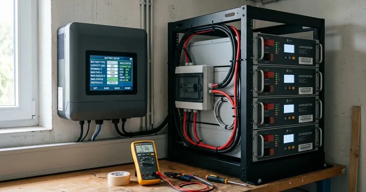
To correctly pair a solar inverter with Dyness LiFePO4 batteries (such as the B4850, BX51100, and DL5.0C), you must configure master module DIP switches to match the inverter brand's communication protocol and select the corresponding lithium profile in the inverter settings menu. When closed loop CAN or RS485 communication is established, the Dyness BMS automatically dictates live charge current limits, cutoffs, and State of Charge (SOC) to the inverter.
The primary setup step is configuring the Master battery DIP switches (0010 for the CAN group, DIP switch 2 ON for Axpert and Growatt SPH/SPA, or 0110 for Growatt SPF over RS485), running a pin-to-pin RJ45 lead from the master battery's comms port to the inverter, and selecting the dedicated Dyness profile on your inverter.
Dyness Inverter Pairing and Settings Table
The table below summarizes verified configuration parameters across major solar inverters sold in Pakistan:
Inverter Platform (PK) | Battery Chemistry / Mode | Protocol / Code Setting | Charge Voltage Limit | Float / Standby Voltage | Master DIP Switch | Comms Protocol | Source |
|---|---|---|---|---|---|---|---|
Solis S5/S6 & RHI 5G | Battery Select: "Dyness LV" | Advanced Settings (password 0010) → Storage Energy Set | Follows the BMS (CVL 56.5 V on 51.2 V models) | Follows the BMS | 0010 (DIP 3 ON) | CAN | Solis Service Guide |
Deye SUN-xK-SG0xLP1 Hybrid | Batt Mode: "Lithium" | Batt Set3 → Lithium Mode "00" (CAN) | Follows the BMS | Follows the BMS | 0010 (DIP 3 ON) | CAN | DIP: Dyness manuals; menu path: installer-documented |
Growatt SPF 3000–5000 ES | Program 05 = "LI" | Prog 36 = "L01" (RS485, per Growatt guide); "L52" (CAN) is community-reported | 53.5 V (48V) / 56.5 V (51.2 V) if falling back to "USE" | Follows the BMS | 0110 (RS485, official) / 0010 (CAN, community-reported) | RS485 or CAN | Growatt Setup Guide; installer forums |
Voltronic Axpert King/VM III | Program 05 = "LIb", or "PYL" on some firmwares (community-reported) | Sub-protocol where prompted | Follows the BMS when linked | Follows the BMS | DIP 2 ON (#2 ON) | CAN Bus | Official List (DIP/models); Community Forums (Prog 05) |
Victron MultiPlus / GX | Battery monitor auto-selects "DYNESS-L" | DVCC ON; charge current/voltage limits OFF | CVL 53.5 V (48V) / 56.5 V (51.2 V) | Float 51.5 V (48V) / 54.5 V (51.2 V) | 0010 (factory default) | VE.Can, CAN-bus BMS 500 kbit/s | Victron Dyness Manual |
Manual Mode (No Comms) | Voltage sensing "USE"/"USER" mode | No BMS protocol selected | 53.5 V (48V B4850) / 56.5 V (51.2 V) | Not published by Dyness for standalone voltage mode | — (comms unused) | None (voltage sensing) | Dyness Product Manuals |
Charge voltages are the Dyness recommended values per family: 53.5 V for 48V B4850 modules, 56.5 V for 51.2 V BX51100 / DL5.0C modules (referenced to 25°C; optimal ambient 15–30°C, charging window 0–55°C). The float and absorption numbers in the Victron row come from the official Dyness–Victron setup manual and are specific to VEConfigure; Dyness does not publish equivalent float targets for the other platforms, which are meant to run closed loop and take their limits from the BMS. Figures as of August 2026.
Step by step inverter pairing walkthrough
Follow these sequential steps to commission a Dyness battery bank with your solar inverter:
- Configure Master Battery DIP Switches:
- Identify the Master battery (the module wired directly to the inverter comms port).
- Set the master DIP switches according to your inverter: 0010 for Solis/Deye/Victron and the rest of the CAN group, DIP switch 2 ON (#2 ON) for Axpert and Growatt SPH/SPA, or 0110 for Growatt SPF over RS485. Ensure all slave modules remain at 0000.
- Connect Communication Cabling:
- Plug a pin-to-pin RJ45 patch lead into the Master battery's comms port — the master CAN IN port in both the Solis and Deye setups — and connect the other end to the inverter BMS/CAN port.
- Check the pin assignment in your own model's manual before trusting a generic lead. Dyness does not use one pinout across the range: on the B4850 comms port pin 4 is CANH and pin 5 is CANL, with 485A on pin 1 and 485B on pin 3, while the DL5.0C puts 485B on pin 1, 485A on pin 2 and EXT-CANH/EXT-CANL on pins 4 and 5.
- Link the Parallel Battery Modules:
- Chain the slave modules to the master with RJ45 patch leads, following the port sequence printed on your model's comms panel. Every module in the chain except the master stays on DIP 0000.
- Program Inverter Profile:
- Power on the battery bank using the master SW button.
- Enter the inverter settings menu and select the appropriate protocol: "Dyness LV" on Solis, Lithium Mode 00 on Deye (installer-documented), or Program 05 "LI" with Program 36 "L01" on a Growatt SPF — swapping to the community-reported CAN option, Program 36 "L52" with master DIP 0010, if the RS485 link refuses to come up.
- Verify BMS Data Synchronization:
- Check that the inverter LCD screen displays battery SOC percentage and clears communication alarm codes.
Sizing, Expansion Rules, and Current Allocation
When designing and commissioning a Dyness lithium battery bank:
- Current Allocation per Module: For BX51100 and DL5.0C modules (100Ah), Dyness recommends a continuous charge/discharge current of 50A (0.5C). Maximum limits differ by model: the BX51100 allows 75A maximum continuous charge/discharge with a 100A peak (15s), while the DL5.0C allows 75A maximum continuous charge and 100A maximum continuous discharge with a 110A peak (15s). Check your continuous load against the module rating before committing to a single unit: drawing 100A continuous exceeds the 75A continuous ceiling on a BX51100, requiring a second parallel module or capping inverter current instead of relying on BMS over-current protection. The B4850 is a smaller module again — 25A recommended, 50A maximum, 100A peak (15s) — so 48V banks need proportionally more modules.
- Voltage Family Separation: Never mix 48V B4850 modules (42–54V work range) with 51.2 V BX51100 / DL5.0C modules (44.8–57.6 V operating range; ratings referenced to 25°C under the 15–30°C optimal ambient band) in the same battery bank. The two families sit at different voltages across the whole charge curve, and paralleling them lets one family dump current into the other instead of sharing the load.
- Parallel Stacking Limits: Dyness officially supports paralleling up to 30 BX51100 modules or up to 40 B4850 modules in a single low-voltage string (limits are stated per model in each product's documentation).
Platform Rebadging and Practical Inverter Compatibility
Many off-grid and hybrid inverter models sold in Pakistan utilize underlying Voltronic Power OEM platforms (including Axpert VM III, King, and MAX series). When pairing Dyness batteries with these inverters, set Master DIP to switch 2 ON (#2 ON, the setting the Dyness manuals assign to the Voltronic family, which also appears on the official LV compatibility list); community reports from installer forums indicate Program 05 should be set to LIb, or PYL on some firmwares. If the inverter firmware does not support closed loop communication, configure Program 05 to USE with manual voltage parameters (53.5 V for B4850; 56.5 V for BX51100 / DL5.0C; referenced to 25°C under the 15–30°C optimal ambient band).
Two platforms sold in Pakistan are worth naming for what the documentation does not say. Fox ESS does not appear on the Dyness LV compatibility list at all, so there is no official Dyness protocol row to give you. The Inverex Nitrox is officially paired with Inverex's own Power Wall and carries no documented Dyness protocol entry either; if your unit is built on the Voltronic platform the Axpert settings above are the sensible starting point, but treat that as unlisted and confirm firmware compatibility with your installer before commissioning.
For communication troubleshooting, refer to our walkthrough on Dyness battery communication fault fixes. To decode LED status patterns, see Dyness alarm and SOC light meanings. For inverter alarm troubleshooting, review our inverter error code glossary.
Safety: Working with LiFePO4 Lithium Battery Systems
Observe these mandatory safety protocols during inverter configuration and battery commissioning:
- Indoor IP20 Installation: Dyness residential modules carry an IP20 rating; install indoors in shaded, dry areas away from direct sunlight, corrosive gas, and conductive dust.
- Operating Temperatures: Maintain room temperatures between 15°C and 30°C, the optimal ambient band in the manuals. The manuals' protection window allows charging from 0°C to +65°C and discharging from −20°C to +65°C, with the BMS stopping charge or discharge outside that window and recovering automatically; note the BX51100 datasheet rates the battery more tightly at 0–55°C charging and −20–55°C discharging, so design to the datasheet figure rather than the protection trip point.
- Electrical Isolation & Terminal Work: Always disconnect AC grid inputs and PV isolators, kill power first, and use insulated tools before handling communication or DC power wiring (a spanner across battery terminals shorts hundreds of amperes). Before closing the DC battery breaker, measure terminal voltage with a multimeter to confirm voltage exceeds 42V and verify correct DC polarity. Circuits under 48V/51.2V must meet SELV per IEC 60950 (with operating voltages referenced to 25°C conditions).
When to call a technician instead
Contact a certified solar installer under the following conditions:
- The inverter displays persistent communication loss after verifying RJ45 pinout and protocol selection.
- The master battery trips on over-current or short-circuit protection when inverter AC loads activate.
- Warranty processing: Dyness dealers in Pakistan advertise a 10-year manufacturer warranty, and at least one Karachi/Lahore dealer adds a 2-year local replacement warranty on top. Both terms are distributor-reported rather than confirmed against a published Dyness warranty document, so get the cycle and warranty conditions in writing from your seller before you need them. Professional installation records ensure smoother claim handling.
For professional maintenance standards, consult our guide on when to call a solar technician and our guide on lithium battery inverter compatibility errors.
Figures as of August 2026.
Still showing the fault? Book a technician
If the steps above did not clear it, tell us the inverter or battery and the exact code. We pass it to a technician who covers your city; visit charges are quoted before they come.
How this pays for the site: the technician or verifier pays SolarNevs a fixed introduction fee. Nobody pays to be recommended, and you are free to use our free guides instead.
Frequently asked questions
What master DIP switch setting connects Dyness batteries to Solis and Deye inverters?
Set the master battery DIP switches to 0010 (DIP 3 ON). This is the CAN setting Dyness lists for Solis, Deye, GoodWe, Victron, SMA, SOFAR, SolaX, Luxpower and others. On Victron GX units the link runs at 500 kbit/s. All slave batteries must remain at 0000.
What are the recommended charge voltages for Dyness 48V vs 51.2 V batteries?
Voltage setpoints are referenced to 25°C under the 15–30°C optimal ambient band (standard charging window is 0–55°C per datasheet; BMS halts charging outside 0 to +65°C). For 48V B4850 modules, the recommended charge voltage is 53.5 V (operating range 42–54V). For 51.2 V DL5.0C and BX51100 modules, the recommended charge voltage is 56.5 V (operating range 44.8–57.6 V).
How do I configure a Growatt SPF 5000 ES inverter for Dyness batteries?
Set Program 05 to 'LI'. Growatt's own lithium guide pairs this with Program 36 = 'L01' over RS485, which matches the Dyness master DIP setting 0110. Installers on solar forums report that the RS485 link can be unreliable with the Dyness cable pinout and report community-documented success instead by switching to CAN with Program 36 = 'L52' and master DIP 0010.
What battery setting should I select on a Solis hybrid inverter for Dyness?
In Solis Advanced Settings (password 0010), navigate to Storage Energy Set → Battery Select and choose 'Dyness LV'. Then set the Overdischarge SOC and Forcecharge SOC values, and run a pin-to-pin RJ45 lead from the master battery's CAN IN port to the Solis battery port with the master DIP at 0010 and slaves at 0000.
Can Dyness batteries pair with Inverex Nitrox inverters?
Dyness batteries are not officially listed on Inverex Nitrox protocol menus; the Nitrox officially pairs with the Inverex Power Wall. If your inverter is built on a Voltronic/Axpert platform, the Axpert settings may apply, but this pairing is not officially listed — confirm firmware compatibility with your installer before commissioning.
References
- Dyness LV Inverter Compatibility List 2024 — accessed 23 August 2026
- Dyness DL5.0C User Manual PDF — accessed 23 August 2026
- Dyness B4850 User Manual PDF — accessed 23 August 2026
- Dyness BX51100 Datasheet PDF — accessed 23 August 2026
- Solis Service Dyness B4850 and RHI Setup Guide — accessed 23 August 2026
- Dyness and Victron Inverter Setup Manual — accessed 23 August 2026
- Growatt SPF 5000ES Lithium Setup Guide — accessed 23 August 2026
- Deye Hybrid Inverter Dyness Battery Connection Guide — accessed 23 August 2026
Related guides
More from inverter errors & fixes.