SolaX Power Smart Meter Wiring and Export Control Guide
Updated 6 September 2026 · By SolarNevs Research Desk, Dealer surveys + verified sources · 2 sources · Method ↗
Key Takeaways
- Connect RS485 differential communication wires A and B from the smart meter to the Meter port on the inverter.
- Install Current Transformer (CT) clamps with arrows pointing towards the household loads away from the grid incomer.
- Enable Export Control in SolaX settings and configure User Value export power limit to 0 Watts for zero feed-in.
- Ensure complete AC circuit isolation and lock-out before installing CT clamps on live busbars.
How to wire your SolaX smart meter and set up export control
Properly wiring your SolaX smart meter and configuring export control ensures your solar energy system operates safely and in compliance with grid regulations in Great Britain. This guide details the connections for Eastron SDM630/SDM120 and Chint DTSU666/DDSU666 smart meters, along with essential inverter settings for managing power export.
Understanding smart meters and export control
A smart meter, such as the Eastron SDM630 or Chint DTSU666, measures the flow of electricity in your property. When paired with a SolaX inverter, it provides real-time data on consumption and generation, enabling the inverter to manage power export to the grid. Current Transformer (CT) clamps are key components of this system, measuring the current flowing through your main electrical cables. The inverter communicates with the smart meter using the RS485 Modbus RTU protocol, allowing it to receive data and adjust its output based on your configured export limits. Export control, often set to "zero feed-in," prevents your solar system from sending excess power back to the grid, which may be a requirement in certain installations or preferred for specific tariff structures.
Step-by-step wiring and configuration for SolaX smart meters
Follow these steps to correctly install and configure your SolaX smart meter for export control.
Step / Component | Technical Procedure & Requirement | Expected System Outcome |
|---|---|---|
1. Electrical Isolation | Isolate main AC supply and inverter AC/DC isolators; lock-out | Safe work environment free of electrical shock hazards |
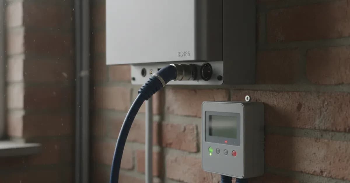
2. RS485 Data Cabling | Connect differential wires A and B to inverter Meter port | Noise-free Modbus RTU communication via shielded twisted-pair |
3. CT Clamp Orientation | Align arrow towards household loads (away from grid incomer) | Prevents inverted readings and false negative power flow |
4. Sensor Mode Selection | Choose Meter or CT mode in inverter advanced menu | Aligns firmware processing with physical sensor hardware |
5. Export Power Limit | Enable Export Control and set User Value to 0 Watts | Enforces dynamic zero feed-in compliance with local grid rules |
Step 1: Prioritise safety and isolate power
Before beginning any wiring work, it is critical to ensure electrical safety. "Ensure complete AC circuit isolation and lock-out before installing CT clamps on live busbars." This prevents electric shock and damage to equipment. Turn off all relevant circuit breakers, including the main AC supply to your property and the inverter's AC isolator. Verify that no power is present using a suitable voltage tester.
Step 2: Connect RS485 communication wires
The smart meter communicates with the SolaX inverter via an RS485 connection. "Connect RS485 differential communication wires A and B from the smart meter to the Meter port on the inverter." It is important to use the correct type of cable for this connection. "Maintain shielded twisted-pair cabling and verify proper RS485 communication baud rate settings." This type of cable helps prevent electrical interference and ensures reliable data transfer.
Step 3: Install Current Transformer (CT) clamps
CT clamps measure the current in your main supply cables. Correct orientation is vital for accurate readings. "Install Current Transformer clamps with arrows pointing towards the household loads away from the grid incomer." This ensures the inverter correctly interprets the direction of power flow. If the CT clamp is installed incorrectly, you may observe "negative power flow during high household consumption," which indicates an inverted CT clamp installation.
Step 4: Configure inverter export control settings
Once the physical connections are made, you need to configure the SolaX inverter's settings to enable export control. "Enable Export Control in SolaX settings and configure User Value export power limit to 0 Watts." This setting instructs the inverter to limit its output so that no power is exported to the grid. Additionally, in SolaX meter setups, you must "select either Meter or CT mode in the inverter advanced settings menu depending on physical sensor type." This tells the inverter which type of external measurement device it is using.
Step 5: Verify operation
After configuration, monitor your inverter's display or the SolaX monitoring portal to ensure the system is operating as expected. Check for consistent power readings and confirm that no power is being exported to the grid if zero export was configured. If you notice unexpected readings, re-check the CT clamp orientation as described in Step 3.
What you can check yourself, and what you cannot
As a homeowner, you can perform several checks to ensure your SolaX smart meter and export control system are functioning correctly:
- Visual Inspection: You can visually check that the RS485 wires are securely connected to the correct terminals (A and B) on both the smart meter and the inverter's Meter port.
- CT Clamp Orientation: You can verify that the arrows on your CT clamps are pointing towards your household loads and away from the grid incomer.
- Inverter Settings: You can navigate through your SolaX inverter's menu to confirm that "Export Control" is enabled and the "User Value" export power limit is set to "0 Watts." You can also check that the correct "Meter" or "CT mode" is selected.
- Monitoring Data: You can review the real-time data on your inverter's display or through the SolaX monitoring platform to observe power flow and confirm that no power is being exported.
However, certain tasks should only be performed by a qualified and accredited installer:
- Internal Wiring Modifications: Any work requiring opening the inverter's enclosure or modifying its internal wiring.
- Grid Protection Settings: Changing grid protection parameters, which are set by an accredited installer to comply with local network rules.
- Troubleshooting Complex Faults: If communication errors persist despite verifying basic connections and settings, or if the inverter displays fault codes not related to simple wiring issues.
- Live Busbar Work: Any installation or adjustment of CT clamps on live busbars without proper isolation and lock-out procedures. "Ensure complete AC circuit isolation and lock-out before installing CT clamps on live busbars."
What the published sources do not tell you
While the provided information covers essential wiring and configuration, some specifics are not detailed in general documentation:
- Specific Baud Rates: Official scheme guidelines mentions verifying RS485 communication baud rate settings but does not provide the exact baud rate value for specific SolaX inverter models or smart meters. This information is typically found in the inverter's detailed installation manual.
- Exact Menu Paths: The precise navigation path within the SolaX inverter's display menu to reach "Export Control" or "Meter/CT mode" settings can vary slightly between different SolaX inverter series or firmware versions. Users should consult their specific inverter's manual for exact menu structures.
- Advanced Troubleshooting Codes: Beyond the "negative power flow" indicator for inverted CT clamps, specific diagnostic codes for RS485 communication failures or meter errors are not listed. These would typically be found in a comprehensive troubleshooting guide for the inverter or smart meter.
- Local Distribution Network Operator (grid operator) Requirements: While SolaX inverters are "Compatible with standard single-phase and three-phase electrical distribution systems globally" and "Complies with international microgeneration safety and grid protection standards," specific local grid operator requirements for connection and export limits in Great Britain are not detailed. These can vary by region and may require specific approvals or settings beyond basic zero export.
Add a battery at a surveyed price
Installers quote supply and fitting of the battery on this page for your existing or new system.
How this pays for the site: installers pay SolarNevs a fixed introduction fee when we pass them a genuine enquiry. They cannot pay to appear higher, and our surveyed prices are published before any introduction. You can also take our dated price tables straight to any installer.
Frequently asked questions
How do I connect the SolaX smart meter to the inverter?
Connect the RS485 differential communication wires A and B from the smart meter to the Meter port on the SolaX inverter. Use shielded twisted-pair cabling for reliable communication.
Which way should the CT clamp arrow point during installation?
Install Current Transformer (CT) clamps with their arrows pointing towards the household loads and away from the grid incomer. Incorrect orientation can lead to negative power readings.
How do I set up zero export with a SolaX inverter?
To set up zero export, enable Export Control in your SolaX inverter's settings. Then, configure the User Value export power limit to 0 Watts. This prevents power from being sent to the grid.
What indicates an incorrectly installed CT clamp?
Negative power flow displayed during periods of high household consumption indicates that the CT clamp installation is inverted. Check the arrow orientation and correct it if necessary.
What type of communication cable is recommended for SolaX smart meters?
Maintain shielded twisted-pair cabling for the RS485 communication between the smart meter and the SolaX inverter. This helps ensure stable data transmission and reduces interference.
References
- SolaX DTSU666/DTSU666-CT Three-Phase Smart Meter User Manual — accessed 27 August 2026
- SolaX Export Control Function (Support Guide) — accessed 27 August 2026
Related guides
More from what to buy — and how not to get cheated.