Deye and Sunsynk CT Clamp and Modbus Energy Meter Wiring Guide
Updated 15 September 2026 · By SolarNevs Research Desk, Dealer surveys + verified sources · 2 sources · Method ↗
Key Takeaways
- CT clamp arrows must point towards the home loads, away from the grid, for correct power flow detection.
- A backwards-installed CT clamp will cause your inverter to incorrectly export power to the grid.
- Modbus energy meters like the Eastron SDM630 or Chint DTSU666 require specific RS485 communication settings.
- All electrical work involving main distribution boards or inverter connections must be performed by a registered person.
Understanding CT Clamps and Modbus Energy Meters
Many South African homes use solar inverters to reduce reliance on the grid, especially during load-shedding. To manage your solar power effectively, your Deye or Sunsynk inverter needs to know how much electricity your home is consuming and how much is being imported from or exported to the grid. This is achieved using either a Current Transformer (CT) clamp or a Modbus energy meter.
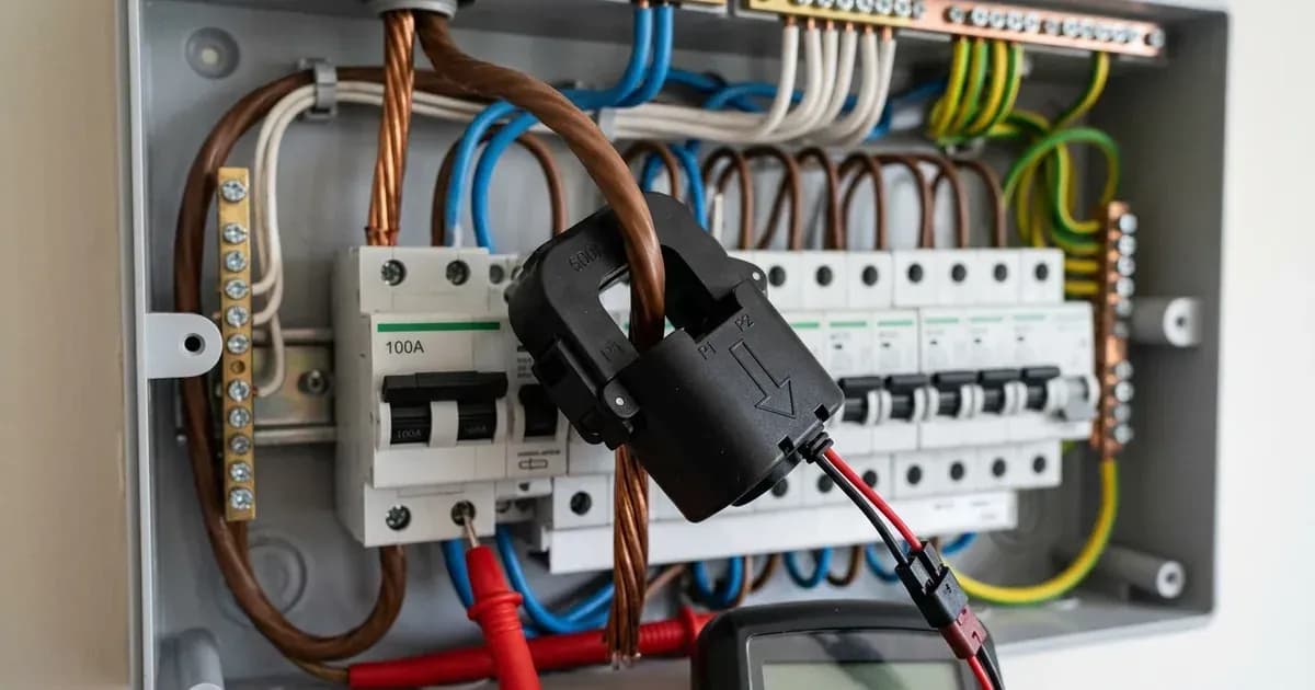
A CT clamp measures the current flowing through a conductor without direct electrical contact. It typically clips around the main incoming live grid conductor. The inverter uses this measurement to understand the real-time power flow, enabling it to dynamically balance solar generation, battery charging, and zero-export control.
For more complex three-phase systems, or when more precise data is required, a dedicated Modbus energy meter is used. This device connects directly into the electrical system and communicates with the inverter via an RS485 serial connection, providing detailed power consumption and generation data.
Wiring Your CT Clamp Correctly
Correct installation of your CT clamp is critical for your Deye or Sunsynk inverter to function as intended. The primary purpose is to tell the inverter whether your home is importing power from the grid or exporting excess solar power.
- Identify the Main Incoming Live Grid Conductor: This is the cable that brings electricity from your utility meter into your home's main distribution board.
- Orient the CT Clamp: "Install split-core CT clamps on the main incoming live grid conductor with the arrow pointing towards the home loads (away from grid)." This ensures the inverter correctly interprets the direction of power flow.
- Connect Signal Wires: "Connect CT white signal wire to positive (+) terminal and black wire to negative (-) terminal on the inverter Meter/CT port." Maintaining this polarity is essential for accurate readings.
- Position the CT: "The energy meter or CT must be installed directly after the utility main revenue meter before any load distribution sub-panels." This ensures it measures the total power flow for the entire property.
Connecting a Modbus Energy Meter
For three-phase installations, or when a Modbus meter is preferred, the connection involves specific wiring and communication settings.
- Select a Compatible Meter: "For three-phase systems, connect an Eastron SDM630 or Chint DTSU666 Modbus meter via shielded twisted-pair cable to RS485 pins." These meters are designed to integrate with Deye and Sunsynk inverters.
- RS485 Wiring: Use a shielded twisted-pair cable for the RS485 connection. Connect the A and B terminals of the meter to the corresponding A and B (or Data+ and Data-) terminals on your inverter's RS485 port.
- Communication Settings: "Set meter Modbus communication parameters to Address 001 and Baud Rate 9600 bps for seamless inverter synchronization." The Modbus communication protocol uses 8-N-1 (8 data bits, no parity, 1 stop bit).
- Meter Position: Similar to CT clamps, "The energy meter or CT must be installed directly after the utility main revenue meter before any load distribution sub-panels."
- Interference Prevention: "Keep Modbus energy meter RS485 cables segregated from high-voltage DC battery cables to prevent electromagnetic interference." This ensures reliable communication. In noisy electrical environments, ground the shield of the RS485 communication cable at the inverter chassis ground terminal only.
Troubleshooting Common Wiring Issues
Incorrect wiring of CT clamps or Modbus meters can lead to unexpected behaviour from your inverter. One of the most common issues is a reverse CT clamp.
Component / Issue | Specification / Meaning | Action / Guidance |
|---|---|---|
CT Clamp Orientation | "Install split-core CT clamps on the main incoming live grid conductor with the arrow pointing towards the home loads (away from grid)." | Ensure the arrow on the CT clamp points away from the grid and towards your home's electrical loads. |
CT Signal Wire Polarity | "Connect CT white signal wire to positive (+) terminal and black wire to negative (-) terminal on the inverter Meter/CT port." | Verify that the white wire is connected to the positive (+) terminal and the black wire to the negative (-) terminal on the inverter. |
Reverse CT Diagnostic Symptom | "If the CT is installed backwards, the inverter incorrectly reads export as import, causing unexpected battery discharge into the grid." | If your battery is discharging into the grid when it should be charging or supplying your home, check the CT clamp orientation and polarity. Correct the arrow direction or swap the signal wires. |
Modbus Communication Settings | "Set meter Modbus communication parameters to Address 001 and Baud Rate 9600 bps for seamless inverter synchronization." | If the inverter is not communicating with the Modbus meter, check the meter's address and baud rate settings. Ensure they match the inverter's requirements. |
CT Cable Extension | "CT signal cables can be extended up to 20 meters using twisted-pair shielded cable without significant signal attenuation." | For longer runs, ensure you use twisted-pair shielded cable to maintain signal integrity. Avoid exceeding 20 metres without professional advice. |
What You Can Check Yourself, and What You Cannot
You can safely check the physical orientation of your CT clamp and the colour-coding of the signal wires at the inverter's connection point. You can also verify the Modbus communication settings on the energy meter's display, if accessible.
However, any work that involves opening the main electrical distribution board, connecting or disconnecting wires within the inverter, or working on live electrical circuits must be performed by a registered electrical professional. "De-energize main electrical distribution board and verify zero voltage with an approved multimeter before clamping CT sensors." Failing to do so can result in serious injury or death. In South Africa, such work also requires a Certificate of Compliance (CoC) issued by a qualified electrician to ensure safety and regulatory adherence.
What the Published Sources Do Not Tell You
While the manufacturer provides clear guidelines for wiring, some practical considerations are not explicitly detailed in the primary documentation. For instance, in multi-inverter parallel setups, the documentation states that "the master inverter reads the external meter and coordinates slave inverters via CAN bus." However, the specific configuration steps within the inverter's menu to designate a master and manage the CAN bus communication for external metering are often found in separate, more detailed installation manuals or require specific firmware versions.
Additionally, while general advice is given to segregate RS485 cables from high-voltage DC battery cables, the precise grounding strategy for the RS485 shield in extremely noisy electrical environments is not always fully covered. In such cases, grounding the shield of the RS485 communication cable at the inverter chassis ground terminal only can help mitigate interference, but this specific detail may not be in the general wiring guides.
Still showing the fault? Book a technician
If the steps above did not clear it, tell us the inverter or battery and the exact code. We pass it to a technician who covers your city; visit charges are quoted before they come.
How this pays for the site: the technician or verifier pays SolarNevs a fixed introduction fee. Nobody pays to be recommended, and you are free to use our free guides instead.
Frequently asked questions
Which way should the CT clamp arrow point on Deye and Sunsynk inverters?
Install split-core CT clamps on the main incoming live grid conductor with the arrow pointing towards the home loads, away from the grid.
What happens if a CT clamp is installed backwards on a Deye or Sunsynk inverter?
If the CT is installed backwards, the inverter incorrectly reads export as import, causing unexpected battery discharge into the grid.
What type of Modbus energy meters are compatible with Deye and Sunsynk inverters?
For three-phase systems, compatible Modbus meters include the Eastron SDM630 or Chint DTSU666, connected via shielded twisted-pair cable to RS485 pins.
What are the Modbus communication settings for Deye and Sunsynk inverters?
Set meter Modbus communication parameters to Address 001 and Baud Rate 9600 bps for seamless inverter synchronization.
Can I extend the CT signal cable for a Deye or Sunsynk inverter?
Yes, CT signal cables can be extended up to 20 metres using twisted-pair shielded cable without significant signal attenuation.
References
- Deye SUN-SMART-CT01 Wireless Communication CT Installation/User Manual — accessed 27 August 2026
- Eastron SDM630-Modbus V2 User Manual (Eastron Electronic Co.) — accessed 27 August 2026
Related guides
More from inverter errors & fixes.