Sunsynk MAX 16kW Single-Phase Hybrid Inverter Installation and CT Clamp Wiring Guide
Updated 7 September 2026 · By SolarNevs Research Desk, Dealer surveys + verified sources · 2 sources · Method ↗
Key Takeaways
- Sunsynk MAX 16kW single-phase inverters require a Current Transformer (CT) clamp for grid monitoring and generator export control.
- The CT clamp connects to pins 3 and 4 on single-phase inverters, with specific polarity.
- Correct CT clamp orientation and polarity verification are critical for accurate grid readings.
- Extending CT cables requires specific material and careful routing to avoid interference.
Understanding the Sunsynk MAX 16kW Single-Phase Hybrid Inverter Installation
The Sunsynk MAX 16kW single-phase hybrid inverter is designed for solar energy systems operating on a standard distribution infrastructure grid, common in Pakistan. While specific electrical ratings and a detailed installation manual for the 16kW MAX model were not available in the provided sources, the general principles for Sunsynk single-phase inverters, particularly regarding Current Transformer (CT) clamp installation, are consistent. Accurate current sensing is fundamental for the inverter to manage energy flow between the solar array, batteries, loads, and the utility grid, ensuring efficient operation and compliance with local grid requirements.
Critical Role of the Current Transformer (CT) Clamp
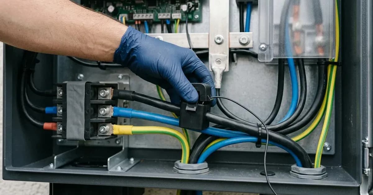
A Current Transformer (CT) Clamp is a sensor that allows the inverter to detect current passing through a cable and which direction this current is flowing. For Sunsynk single-phase inverters, a single CT clamp is typically supplied and is essential for several functions. It enables the inverter to monitor grid consumption and export, preventing unwanted power feedback to the grid or to a connected auxiliary generator. When using the system with a generator connected to the GRID terminals, a CT clamp must be used so you are able to control the export and prevent electricity being fed back into the generator.
Sunsynk Single-Phase CT Clamp Wiring and Polarity
Correct wiring of the CT clamp is crucial for the Sunsynk inverter to accurately measure current flow. For single phase inverters the CT clamp tails should be connected to pin 3 and pin 4 in the inverter. With the white tail in pin 3 and the black tail in pin 4. The physical orientation of the clamp on the live conductor is also important: The clamp should be clipped onto the live tail coming from the property meter and the arrow should be pointing towards the inverter.
Safety Note: Before attempting any wiring, ensure all power sources to the inverter are isolated. This includes turning off the AC grid supply, opening any DC PV array isolators, and disconnecting battery power. Always use appropriate Personal Protective Equipment (PPE), such as insulated gloves and eye protection. Work inside the inverter enclosure should only be performed by qualified personnel.
Setting / Parameter | Specification / Action | Technical Reference |
|---|---|---|
CT Clamp Quantity (Single-Phase) | One CT clamp supplied with single phase inverters. | Sunsynk Support Articles |
CT Clamp Connection (Single-Phase) | White tail to pin 3, black tail to pin 4 in the inverter. | Sunsynk Support Articles |
CT Clamp Orientation | Arrow on clamp points towards the inverter, clipped onto the live tail from the property meter. | Sunsynk Support Articles |
Verifying CT Clamp Polarity and Coil Readings
After physical installation, it is necessary to verify the CT clamp's polarity to ensure accurate readings. An incorrect polarity will result in negative current readings, which can be resolved by reversing the clamp's direction.
Initial Polarity Check:
- Ensure the DC switch on the side of the inverter is ‘OFF’.
- Disable ‘use timer’ in the system mode settings.
- Observe the CT reading on the inverter's display. It should be positive.
- If this value is negative there is a polarity issue with the CT, this can be resolved by changing the clamp direction.
CT Coil Reading Verification Procedure: This procedure helps confirm the CT clamp is reading correctly by isolating other power sources.
- Isolate PV Input: Turn Off the PV Isolator to remove the PV Input.
- Stop Battery Discharge: In System Mode > System1 Timers, set Target SOC of current time to 100% to stop the Batteries discharging.
- Access System Status Screen: Return to Display Home Screen (with the 4x Dials) and touch AC Load Dial to view System Status Screen.
- Verify Grid Power Reading: On Status Screen view the Grid Power section (Upper middle). The HM or CT Reading MUST be a positive reading.
Safety Note: When working with PV arrays, always ensure the PV isolator is open and locked out before disconnecting or connecting any wiring. Batteries can store significant energy; ensure they are isolated and discharged to a safe level before working on their connections.
CT Clamp Cable Management and Ratio Configuration
The integrity of the CT clamp signal is dependent on proper cable management and correct ratio configuration within the inverter settings.
Cable Length and Extension: The cable length between the inverter and the CT clamp should ideally be no more than 10 meters, although in some circumstances this can be extended up to 15 meters. If extension is necessary, the cable used must be made of copper and an equal thickness or thicker to the existing CT cables.
Cable Routing and Interference: The CT cables should also not be run closely paralleled to any AC cables and they should never be contained in the same trunking. This prevents electromagnetic interference from affecting the sensitive CT signal, which could lead to inaccurate readings.
CT Ratio Setting: The CT ratio can be set in the inverter under ‘Advanced Settings’. The correct ratio depends on the specific CT clamp model used:
- Standard 100A/50mA CTs: These must be connected in the right-hand side. There is no multiplier on these connections so the standard 2000:1 CT ratio applies (calculated as 100A/0.05A).
- 300A/5A CTs: If using the 300A/5A CTs these must be connected on the left-hand CT connections in the inverter. The CT ratio has a x100 multiplier, so the ratio is calculated as follows: CT ratio = (300A/5A) *100 CT ratio = 6000:1.
Installation Safety and Switchgear Requirements
A safe and compliant installation of the Sunsynk MAX 16kW single-phase hybrid inverter requires adherence to fundamental electrical safety practices and appropriate switchgear.
Isolation Sequence: Before any work on the inverter or associated wiring, a strict isolation sequence must be followed:
- Disconnect the AC utility grid supply by opening the main AC breaker.
- Open all DC PV array isolators to de-energize the solar strings.
- Open the DC battery breaker to isolate the battery bank.
- Verify zero voltage at all terminals using a suitable multimeter.
- Wait for the inverter's internal capacitors to discharge (refer to the inverter manual for specific discharge times, which were not available in the provided sources).
- Apply Lock-Out/Tag-Out (LOTO) procedures to prevent accidental re-energisation.
DC Breaker Sizing: While specific sizing for a 275A DC battery breaker or any other DC breaker for the Sunsynk MAX 16kW inverter was not found in the provided documents, appropriate DC circuit breakers are essential for battery and PV array protection. These must be correctly sized by a qualified electrician based on the battery bank's maximum discharge current, PV array's short-circuit current, and the inverter's maximum input currents.
Earthing Requirements: All metal enclosures and non-current-carrying metal parts of the solar installation, including the inverter chassis, PV array frames, and mounting structures, must be properly earthed (grounded) to a common earthing point. This provides a safe path for fault currents and protects against electric shock.
Authorized Technician Boundaries: Installation, commissioning, and any internal work on the inverter, especially involving high-voltage DC or AC connections, should only be performed by certified and experienced solar technicians or electricians. Attempting such work without proper qualifications and safety training can result in severe injury or damage to equipment.
What the published sources do not tell you
The provided documentation for the Sunsynk MAX 16kW single-phase hybrid inverter has several critical information gaps that users and installers should be aware of:
- Sunsynk MAX 16kW Specific Datasheet/Specifications: No specific electrical ratings (e.g., AC output power, PV input voltage/current, battery voltage range, efficiency) or physical dimensions for the 16kW MAX model were available. This means detailed performance characteristics and compatibility data are not provided.
- 275A DC Battery Breaker Wiring: There is no mention of a 275A DC battery breaker, or any specific DC battery breaker sizing or wiring instructions, for the Sunsynk MAX 16kW inverter or any other inverter model in the fetched documents. Installers must rely on general electrical codes and battery manufacturer specifications for appropriate battery protection.
- Comprehensive AUX Generator Control: While the need for a CT clamp to prevent generator export is mentioned, detailed instructions for AUX generator connection, auto-start/stop settings, or specific control parameters for the Sunsynk MAX 16kW inverter were not found.
- Battery Compatibility and Wiring: No specific battery compatibility list, battery voltage ranges, or detailed wiring instructions for connecting batteries (beyond general CT clamp interaction) were available.
- Error/Fault Codes: A comprehensive list of error or fault codes, their meanings, or troubleshooting steps for the Sunsynk MAX 16kW inverter was not found, which can complicate fault diagnosis.
- Installation Manual: A full installation manual for the Sunsynk MAX 16kW inverter, which would typically cover detailed wiring diagrams, mounting instructions, and comprehensive safety precautions, was not available.
- App/Monitoring Setup: Details regarding the Sunsynk Connect app, Wi-Fi/datalogger setup, or remote monitoring features were not found.
- Firmware Information: No information on firmware versions, update procedures, or specific settings menus (beyond "Advanced Settings" for CT ratio) was available.
These gaps mean that installers may need to consult general Sunsynk documentation for other models or rely on practical experience for aspects not covered by the available CT clamp and generator export control information.
Still showing the fault? Book a technician
If the steps above did not clear it, tell us the inverter or battery and the exact code. We pass it to a technician who covers your city; visit charges are quoted before they come.
How this pays for the site: the technician or verifier pays SolarNevs a fixed introduction fee. Nobody pays to be recommended, and you are free to use our free guides instead.
Frequently asked questions
What is the purpose of the CT clamp on a Sunsynk single-phase inverter?
A Current Transformer (CT) Clamp is a sensor that allows the inverter to detect current passing through a cable and which direction this current is flowing. It is essential for accurate grid monitoring and preventing electricity export back to the grid or a connected generator.
How do I connect the CT clamp to a Sunsynk single-phase inverter?
For single-phase inverters, the CT clamp tails should be connected to pin 3 and pin 4 in the inverter, with the white tail in pin 3 and the black tail in pin 4. The clamp itself should be clipped onto the live tail coming from the property meter, with the arrow pointing towards the inverter.
How can I check if the CT clamp polarity is correct?
With the DC switch on the side of the inverter ‘OFF’ and ‘use timer’ disabled in the system mode settings, the CT reading on the display should be positive. If the value is negative, there is a polarity issue, which can be resolved by changing the clamp direction.
What is the maximum recommended cable length for the CT clamp?
The cable length between the inverter and the CT clamp should ideally be no more than 10 meters, though it can be extended up to 15 meters in some circumstances. Any extension cable must be copper and of equal or thicker gauge.
Where do I set the CT ratio on a Sunsynk inverter?
The CT ratio can be set in the inverter under ‘Advanced Settings’. For a standard 100A/50mA CT, the ratio is 2000:1. If using a 300A/5A CT, it must be connected to the left-hand CT connections, and the ratio is 6000:1.
References
- Sunsynk Support Articles — accessed 29 August 2026
- Sunsynk Support Articles — accessed 29 August 2026
Related guides
More from inverter errors & fixes.