FoxESS Chint Smart Meter Wiring and Zero Export Guide
Updated 6 September 2026 · By SolarNevs Research Desk, Dealer surveys + verified sources · 2 sources · Method ↗
Key Takeaways
- FoxESS Chint DTSU666 (three-phase) and DDSU666 (single-phase) meters use RS485 for communication.
- CT clamp arrows must point towards household loads, away from the grid incomer.
- Zero export is configured via the "Feed-in Limitation" setting in FoxCloud, set to 0 Watts.
- Installing CT clamps on live busbars requires complete AC circuit isolation and lock-out.
Understanding FoxESS Chint Smart Meters for Zero Export
FoxESS inverters, when paired with Chint DTSU666 (three-phase) or DDSU666 (single-phase) smart meters, can precisely monitor energy flow and enforce zero export limits. These meters communicate with the inverter using the RS485 Modbus RTU protocol, providing real-time data on household consumption and grid interaction. This data allows the inverter to adjust its output to match your home's demand, preventing excess solar generation from being sent to the grid.
The smart meter is a critical component for any grid-tied solar system aiming for self-consumption or mandated zero export. It measures the power flowing in and out of your property at the main incomer. This measurement, combined with the inverter's own generation data, enables the system to dynamically manage energy.
Connecting Your FoxESS Chint Smart Meter (RS485 Wiring)
The communication between your FoxESS Chint smart meter and the inverter relies on an RS485 connection. This is a standard serial communication method that uses two wires for data transmission.
RS485 Wiring Steps
- Identify Terminals: Locate the RS485 differential communication wires, typically labelled A and B, on your Chint smart meter.
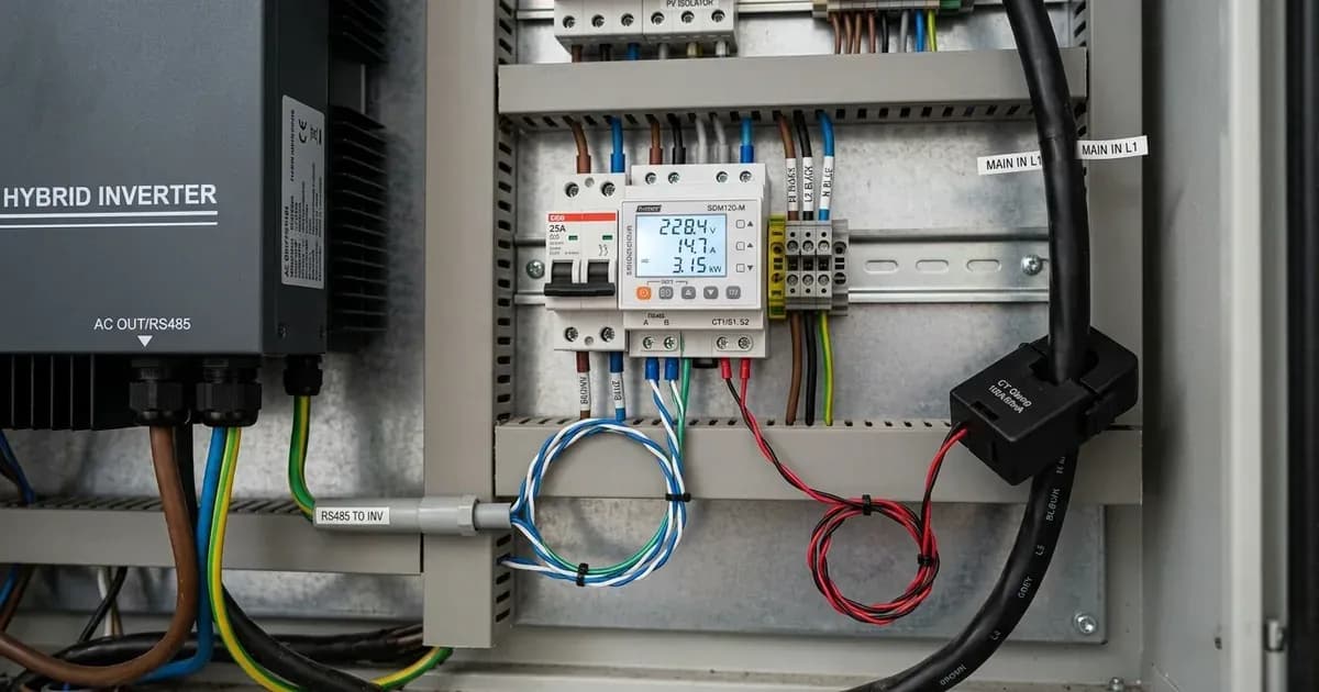
- Inverter Connection: Connect these A and B wires from the smart meter to the corresponding Meter port on your FoxESS inverter. Ensure that wire A from the meter connects to terminal A on the inverter's Meter port, and wire B connects to terminal B.
- Cable Type: For optimal communication integrity, use shielded twisted-pair cabling for the RS485 connection. This helps to minimise electrical interference over longer distances.
- Baud Rate: Verify that the RS485 communication baud rate settings on both the smart meter and the inverter are correctly matched. Incorrect baud rates will prevent communication.
- Earthing: Bond the inverter chassis ground and any battery metal enclosure to the main installation earthing terminal. This ensures electrical safety and proper grounding for the system.
Correct CT Clamp Installation for Accurate Export Limiting
Current Transformer (CT) clamps are essential for the smart meter to measure current accurately. Their correct orientation is vital for the zero export function to work as intended.
CT Clamp Installation Guide
- Placement: Install the CT clamps around the main live conductors at the point where power enters or leaves your property from the grid.
- Orientation: Install Current Transformer clamps with arrows pointing towards the household loads. This means the arrow on the CT clamp should point away from the grid incomer. This orientation ensures the meter correctly interprets the direction of power flow.
- Safety First: Before installing CT clamps on live busbars, ensure complete AC circuit isolation. This involves switching off and locking out the main AC circuit breaker to prevent accidental re-energisation during installation. This is a critical safety step that must not be bypassed.
- Diagnostic Check: After installation, monitor your system's power flow. If you observe a negative power flow reading during periods of high household consumption, it indicates an inverted CT clamp installation. In this scenario, the CT clamp is installed backwards and must be reoriented to correct the measurement.
Configuring Zero Export in FoxCloud
Once your FoxESS Chint smart meter is correctly wired and installed, the final step is to configure the zero export function through the FoxCloud monitoring platform.
Zero Export Configuration Steps
- Access FoxCloud: Log in to your FoxCloud account, either via the web portal or the mobile application.
- Enable Feed-in Limitation: Navigate to the settings section for your inverter. Locate and enable the "Feed-in Limitation" option. This feature is specifically designed to manage and restrict power export to the grid.
- Set Export Power: Configure the maximum allowable export power to 0 Watts. This setting instructs your FoxESS inverter to prevent any surplus solar energy from being sent back to the grid, ensuring that all generated power is either consumed by your household or stored in a connected battery system.
- Monitor Performance: Regularly check your FoxCloud dashboard to ensure the system is operating as expected and that no power is being exported. The platform provides real-time telemetry, allowing you to monitor battery charge/discharge and overall energy management.
What You Can Check and What Requires an Installer
Understanding the boundary between homeowner checks and professional installer work is crucial for safety and system integrity.
System Component / Task | Homeowner Scope (Visual & Cloud) | Accredited Electrician Scope |
|---|---|---|
Telemetry & App Setup | Monitor generation/consumption and enable 0W Feed-in Limit in FoxCloud | Verify grid-protection parameters and statutory export compliance |
Meter & Enclosure | Visual check of external cables and meter status LED | Enclosure access, main switchboard connection, 5-min capacitor discharge |
RS485 Communication | Verify data sync on FoxCloud dashboard | Wire shielded twisted-pair to A/B Meter terminals and match baud rate |
CT Clamps (DDSU666/DTSU666) | Identify inverted CT from negative power flow in app | AC busbar isolation, lock-out, and arrow orientation towards loads |
Three-Phase Integration | View per-phase consumption graphs in app | Phase matching between L1/L2/L3 voltage references and CT clamps |
Earthing & Bonding | Visual check of ground wire integrity | Bond inverter chassis and battery enclosure to main earthing terminal |
What You Can Check Yourself, and What You Cannot
- What you can check yourself: You can visually inspect the smart meter display, check that the communication indicator light is active, and monitor generation/consumption values in the FoxCloud app. You can also visually check external wiring runs for mechanical damage.
- What you cannot do yourself (Authorized Service Work): Never open the inverter enclosure, meter cover, or main switchboard. Enclosure-level work meets a DC bus that stays charged after switch-off. Always isolate PV, battery, and AC breakers and wait at least 5 minutes for internal capacitors to discharge before any authorized service inspection. Initial connection, termination of RS485 communication wires, and CT clamp installation on live busbars must be performed strictly by a qualified and accredited electrician.
What Requires an Accredited Installer
- Live AC Circuit Work: Any installation, adjustment, or troubleshooting involving live AC busbars, main incomers, or the main electrical panel. This includes the initial installation of CT clamps and any reorientation requiring access to live circuits.
- RS485 Terminal Connections: Always isolate PV, battery, and AC breakers and wait the manual's capacitor-discharge time before any inspection requiring opening the unit, and note that opening the unit is authorised-service work. Initial connection and any re-termination of RS485 wires at the inverter or meter must be performed strictly by a qualified and accredited electrician.
- Inverter Internal Settings: Do not attempt to change any internal inverter settings beyond what is accessible and clearly documented in FoxCloud for end-users. Grid-protection settings are set by an accredited installer and changing them can breach your connection agreement.
- Earthing Connections: The bonding of inverter chassis ground and battery metal enclosures to the main earthing terminal is a critical safety measure and must be performed by a qualified professional.
- Phase Matching: For three-phase installations, ensuring phase matching between meter voltage reference terminals (L1, L2, L3) and CT clamp positions is a complex task requiring professional expertise.
What the Published Sources Do Not Tell You
While the provided documentation offers clear guidance on wiring and configuration, some practical details and specific scenarios are not explicitly covered.
The documentation from mcscertified.com does not detail specific RS485 baud rates for the Chint DTSU666 or DDSU666 meters, nor does it specify the exact terminal numbering for the RS485 A and B connections on all FoxESS inverter models. Users may need to consult their specific inverter's manual for precise terminal layouts and default communication settings.
Furthermore, while it mentions "Compatible with standard single-phase and three-phase electrical distribution systems globally," it does not provide specific country-by-country grid code compliance details beyond a general statement about "international microgeneration safety and grid protection standards." Local network operator requirements in Great Britain may have additional nuances not covered by these general statements. The process for obtaining approval from a Distribution Network Operator (grid operator) for grid connection and export limitation is also not detailed, as this is a regulatory process rather than a product specification.
Official scheme guidelines highlights the importance of phase matching in three-phase installations but does not provide a step-by-step guide on how to verify or correct this, implying it is a task for a qualified installer.
Add a battery at a surveyed price
Installers quote supply and fitting of the battery on this page for your existing or new system.
How this pays for the site: installers pay SolarNevs a fixed introduction fee when we pass them a genuine enquiry. They cannot pay to appear higher, and our surveyed prices are published before any introduction. You can also take our dated price tables straight to any installer.
Frequently asked questions
What FoxESS Chint smart meters are covered by this guide?
This guide covers the Chint DTSU666 three-phase smart meter and the Chint DDSU666 single-phase smart meter, both manufactured by FoxESS Co., Ltd.
How do I connect the RS485 communication wires for a FoxESS Chint smart meter?
Connect the RS485 differential communication wires, labelled A and B, from the smart meter directly to the dedicated Meter port on your FoxESS inverter. Ensure correct polarity.
Which way should the CT clamp arrow point during installation?
Install Current Transformer (CT) clamps with the arrow pointing towards the household loads. This means the arrow should point away from the grid incomer, indicating the direction of power flow to consumption.
How do I activate zero export for my FoxESS system?
To activate zero export, enable the 'Feed-in Limitation' feature within your FoxCloud settings. Configure the maximum allowable export power to 0 Watts to prevent energy from being sent to the grid.
What does a negative power flow during high consumption indicate?
A negative power flow reading when your household is consuming significant power indicates an inverted CT clamp installation. This means the CT clamp is installed backwards and needs to be reoriented.
References
- Chint DTSU666/DSSU666 Smart Meter User Manual (meter supplied with FoxESS) — accessed 27 August 2026
- FoxESS FoxCloud 2.0 App User Manual — accessed 27 August 2026
Related guides
More from what to buy — and how not to get cheated.