Deye Auxiliary Smart Load And CT Clamp Wiring Guide
Updated 15 September 2026 · By SolarNevs Research Desk, Dealer surveys + verified sources · 2 sources · Method ↗
Key Takeaways
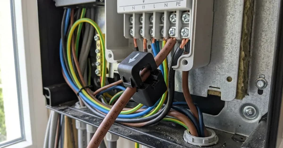
- CT clamps must be installed with arrows pointing towards household loads, away from the grid incomer.
- Ensure the inverter chassis and battery enclosure are properly earthed to the main installation terminal.
- Set the CT ratio to 1:2000 in the Deye inverter's factory settings when using external CT clamps.
- Negative power flow readings during high consumption indicate an inverted CT clamp installation.
How do I correctly wire the Deye auxiliary port and CT clamps for zero export and smart load management?
Correctly wiring the Deye auxiliary port and Current Transformer (CT) clamps is essential for enabling smart load shedding, generator autostart, microinverter AC coupling, and accurate zero export functionality with Deye Hybrid Inverters. These functions rely on precise current measurement and adherence to safety standards. The Deye Hybrid Inverters, such as the SUN-3.6K/5K/8K/10K/12K Series, are designed to integrate these features for residential and commercial energy storage systems in Great Britain.
What is actually going on
The Deye auxiliary port and CT clamps work together to provide the inverter with real-time data about your home's energy consumption and grid interaction. CT clamps are devices that measure the flow of electrical current without direct contact with the conductor. When installed correctly, they sense how much electricity is being imported from or exported to the grid.
The Deye inverter uses this information for several key functions:
- Zero Export: By monitoring the current flow, the inverter can adjust its output to ensure that no excess solar power is sent back to the grid. This is crucial for compliance with connection agreements that may have export limits.
- Smart Load Shedding: If your battery state of charge (SOC) drops too low or grid conditions require it, the inverter can use the auxiliary port to activate or deactivate specific "smart" loads. This helps manage power consumption and prioritise critical appliances.
- Generator Autostart: The auxiliary port can be configured to automatically start a backup generator when the battery reaches a low SOC or during a grid outage, ensuring continuous power supply.
- AC Coupling: For systems with existing microinverters, the auxiliary port can facilitate their integration, allowing the Deye inverter to manage the overall AC power flow.
The accuracy of these functions depends entirely on the correct installation and configuration of the CT clamps and the auxiliary port wiring. Incorrect installation can lead to inaccurate readings, improper system behaviour, and potential safety hazards.
Key Wiring Rules and Standards
The following table outlines critical wiring rules and operating standards for Deye auxiliary port and CT clamp installations, ensuring safe and compliant operation.
Rule / Standard | What it means | What to do |
|---|---|---|
CT Clamp Arrow Orientation towards Load | "Install Current Transformer clamps with arrows pointing towards the household loads away from the grid incomer." | Ensure the arrow on the CT clamp points in the direction of power flow from the grid towards your home's electrical loads. |
Smart Load Off-Grid Power Management | "Bond inverter chassis ground and battery metal enclosure to the main installation earthing terminal." | Connect the metal casing of the inverter and any battery enclosures to your property's main earthing point for safety. |
Zero Export to CT Metering Mode | "Ensure complete AC circuit isolation and lock-out before installing CT clamps on live busbars." | Always de-energise and secure the AC circuit at the main main distribution board before handling or installing CT clamps to prevent electric shock. |
Auxiliary Port Generator AC Input Integration | "The ESS assistant dynamically manages battery charge and discharge based on grid tariffs and load." | While this describes the ESS function, for generator integration, ensure the generator's AC output is connected to the designated auxiliary port input as per the inverter manual. |
Microinverter AC Coupling on Aux Port | "Maintain shielded twisted-pair cabling and verify proper RS485 communication baud rate settings." | If using RS485 for communication with microinverters via the auxiliary port, use appropriate shielded cables and confirm communication settings. |
Smart Load Off SOC and On SOC Setpoints | "Negative power flow during high household consumption indicates inverted CT clamp installation." | If your inverter reports power flowing to the grid when you know you are consuming heavily, check the CT clamp orientation immediately. |
Safe Panel Isolation Protocols | "Ensure complete AC circuit isolation and lock-out before installing CT clamps on live busbars." | Always follow strict safety procedures, including turning off and locking out the main circuit breaker, before working inside electrical panels. |
What you can check yourself, and what you cannot
As a homeowner, there are specific checks you can perform, but many tasks require the expertise of an accredited installer.
What you can check yourself:
- CT Clamp Orientation: Visually inspect the CT clamps to ensure the arrows are pointing towards your household loads, away from the grid incomer. This is a common cause of incorrect readings.
- Negative Power Flow: Monitor your inverter's display or app for any indications of negative power flow (exporting to the grid) when you know your household consumption is high. This suggests an inverted CT clamp.
- Earthing Continuity (Visual): Visually confirm that the inverter chassis and battery enclosures appear to be connected to an earthing point. Do not attempt to test electrical continuity yourself.
- CT Ratio Setting: If you have access to the inverter's user interface, you can verify that the CT ratio is set to 1:2000 for external CT clamps. This is a menu setting, not a physical wiring task.
What you cannot and should not do yourself:
- Working on Live AC Circuits: Never attempt to install or adjust CT clamps on live busbars or any other live AC wiring. This poses a severe risk of electric shock.
- Opening the Inverter Enclosure: Do not open the Deye inverter's main enclosure. This should only be done by authorised service personnel after isolating all power sources (PV, battery, AC grid) and waiting for capacitor discharge time.
- Changing Grid-Protection Settings: Altering grid-protection settings in the inverter can breach your connection agreement with the Distribution Network Operator (grid operator) and compromise grid stability. These settings are configured by accredited installers.
- Complex Wiring Modifications: Any modifications to the physical wiring of the auxiliary port for smart loads, generators, or AC coupling should be performed by a qualified electrician or accredited solar installer.
Always prioritise safety. If you are unsure about any aspect of your Deye inverter installation or wiring, contact a certified professional.
What the published sources do not tell you
While official documentation provides crucial safety and compliance information, it does not offer detailed, step-by-step wiring diagrams or specific instructions for every Deye Hybrid Inverter model.
Specifically, the provided sources do not detail:
- Specific Auxiliary Port Pinouts: The exact terminal assignments for smart load, generator, or AC coupling connections on different Deye inverter models are not provided. These can vary between series (e.g., SUN-3.6K vs. SUN-12K).
- Cable Specifications: The recommended cable gauges, types, or lengths for connecting various auxiliary devices are not specified.
- Detailed Installation Diagrams: Comprehensive wiring diagrams illustrating the physical connection points for each auxiliary function (e.g., how to connect a contactor for smart load shedding) are absent.
- Inverter Menu Navigation: The precise menu paths or button sequences required to set the CT ratio or configure auxiliary port functions within the Deye inverter's user interface are not included.
- Compatibility Lists: Specific models of generators, microinverters, or smart loads that are officially compatible with the Deye auxiliary port are not listed.
For these specific details, it is essential to consult the detailed installation manual provided with your particular Deye Hybrid Inverter model or seek guidance from an accredited Deye installer.
Add a battery at a surveyed price
Installers quote supply and fitting of the battery on this page for your existing or new system.
How this pays for the site: installers pay SolarNevs a fixed introduction fee when we pass them a genuine enquiry. They cannot pay to appear higher, and our surveyed prices are published before any introduction. You can also take our dated price tables straight to any installer.
Frequently asked questions
What are the primary technical requirements for deye auxiliary smart load and ct clamp wiring guide?
Key requirements include compliance with local grid codes, correct equipment certification, and proper electrical isolation.
Who is authorized to install and inspect deye auxiliary smart load and ct clamp wiring guide?
All high-voltage DC, AC grid tie-in, and switchboard modifications must be performed by a qualified, accredited electrical professional.
How is export power limited in deye auxiliary smart load and ct clamp wiring guide?
Export limiting is achieved using certified bidirectional smart meters or power sensors providing dynamic feedback to the inverter system.
References
- Deye SUN-5/6/8/10/12K-SG04LP3 Hybrid Inverter User Manual (PDF) – CT connection, CT ratio 2000:1, Zero Export To CT, Smart Load and GEN port settings — accessed 6 September 2026
- NEPRA (Prosumer) Regulations, 2026 – SRO 251(I)/2026 (PDF): distributed generation interconnection, metering and protection requirements — accessed 6 September 2026
Related guides
More from what to buy — and how not to get cheated.