Solis Eastron Sdm630 Smart Meter Wiring And Zero Export Guide
Updated 15 September 2026 · By SolarNevs Research Desk, Dealer surveys + verified sources · 6 sources · Method ↗
Key Takeaways
- The Eastron SDM630 meter uses Modbus RTU serial communication to connect with Solis inverters for zero export.
- Correct CT clamp orientation is critical: arrows must point towards household loads.
- Zero export is enabled in the inverter's advanced settings by setting the limit to 0 Watts.
- Always isolate AC circuits and follow lock-out procedures before working on live busbars.
How to Set Up Zero Export with Solis and Eastron SDM630
To prevent your solar system from exporting excess power to the grid, you need to correctly wire and configure your Eastron SDM630 three-phase smart meter with your Solis hybrid inverter. This guide details the necessary steps for serial communication, CT clamp placement, and inverter settings.
Understanding Zero Export and Your Smart Meter
Zero export, also known as zero injection, is a function that prevents your solar photovoltaic (PV) system from sending any surplus electricity back to the public grid. This is often a requirement from network operators or for specific tariff arrangements. The Eastron SDM630 smart meter, when paired with a Solis inverter, measures the power flow at your grid connection point. It then communicates this data to the inverter via a serial Modbus RTU connection. The inverter uses this information to dynamically adjust its output, ensuring that only enough power is generated to meet your household's demand, with any excess being stored in batteries or curtailed.
Wiring the Eastron SDM630 Meter to Your Solis Inverter
Accurate wiring is fundamental for reliable zero export functionality. Follow these steps carefully:
- Serial Communication Wiring:
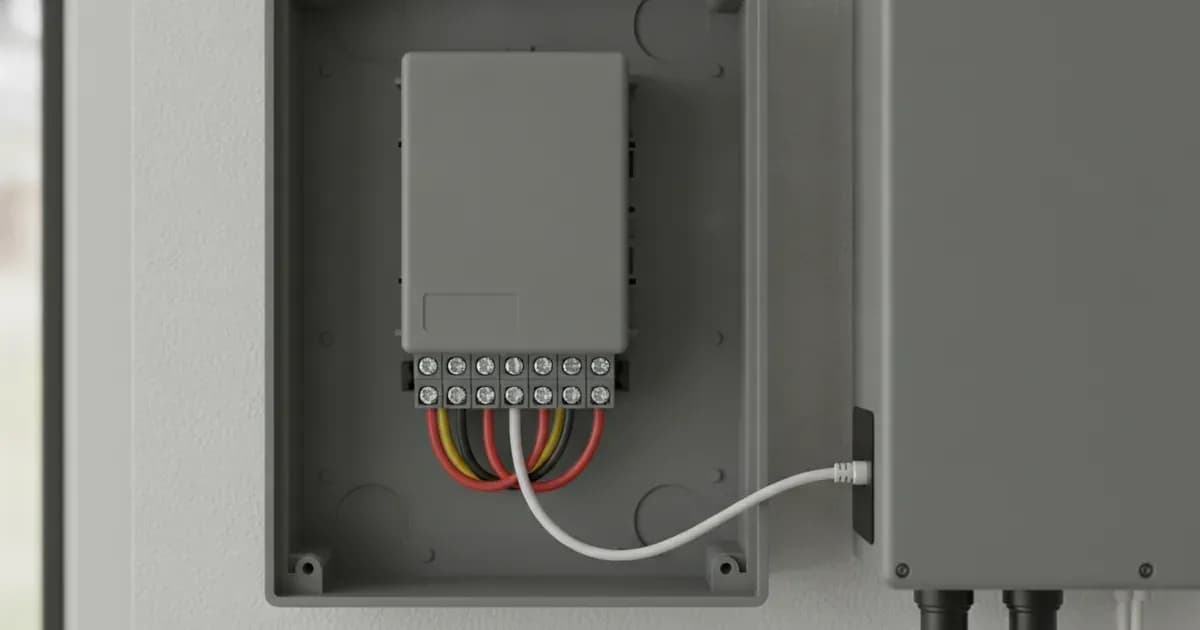
- Connect differential communication wires A and B from the smart meter to the Meter port on the inverter.
- Use shielded twisted-pair cabling to maintain communication integrity and reduce interference.
- CT Clamp Installation and Orientation:
- Install Current Transformer (CT) clamps. These measure the current flowing in your main supply cables.
- The arrows on the CT clamps must point towards the household loads, away from the grid incomer. This ensures the meter correctly identifies the direction of power flow.
Configuring Your Solis Inverter for Zero Export
Once the wiring is complete, you need to configure the inverter's settings:
- Enable Zero Injection:
- Access the inverter's advanced settings menu.
- Enable "Zero Injection."
- Set the export limit power to 0 Watts. This instructs the inverter to prevent any power from being sent to the grid.
- Verify Modbus Settings:
- In the meter's setup menu, verify that the meter address is set to 001.
- Confirm the baud rate is configured to 9600 bps. These settings ensure proper communication between the meter and the inverter.
Diagnosing Common Issues
Issue | What it means | What to do |
|---|---|---|
Negative power flow during high household consumption | Indicates inverted CT clamp installation. | Reverse the CT clamp's direction so the arrow points towards the loads. |
Communication errors or no data from meter | Incorrect wiring, incorrect Modbus settings, or cable issues. | Check communication A/B connections, verify meter address (001) and baud rate (9600 bps), and inspect shielded twisted-pair cabling. |
What you can check yourself, and what you cannot
You can perform visual checks of wiring connections, verify CT clamp orientation, and navigate the inverter's menu to confirm zero export settings and Modbus parameters. However, any work involving live AC circuits or opening the inverter's enclosure should only be performed by a qualified and accredited installer.
Safety First: Mandatory Precautions
- AC Circuit Isolation: Always ensure complete AC circuit isolation and lock-out before installing CT clamps on live busbars. Failure to do so can result in severe injury or death.
- Earthing: Bond the inverter chassis ground and any battery metal enclosure to the main installation earthing terminal. This is crucial for electrical safety.
- Authorised Service: Opening the inverter unit, replacing internal components, or re-pinning connectors is authorised-service work. Isolate PV, battery, and AC breakers, and wait the manual's capacitor-discharge time before any such work.
What the published sources do not tell you
While the documentation provides clear instructions for wiring and configuration, specific network operator requirements for grid connection in Great Britain can vary. These requirements, including any local grid protection standards beyond the general "Certified Anti-Islanding Protection," are often not detailed in general product manuals. Additionally, the exact menu navigation steps for advanced settings may differ slightly between Solis inverter firmware versions, which is not covered in generic documentation. For precise, model-specific menu paths, consult your inverter's specific user manual or the Solis portal.
Add a battery at a surveyed price
Installers quote supply and fitting of the battery on this page for your existing or new system.
How this pays for the site: installers pay SolarNevs a fixed introduction fee when we pass them a genuine enquiry. They cannot pay to appear higher, and our surveyed prices are published before any introduction. You can also take our dated price tables straight to any installer.
Frequently asked questions
What are the primary technical requirements for solis eastron sdm630 smart meter wiring and zero export guide?
Key requirements include compliance with local grid codes, correct equipment certification, and proper electrical isolation.
Who is authorized to install and inspect solis eastron sdm630 smart meter wiring and zero export guide?
All high-voltage DC, AC grid tie-in, and switchboard modifications must be performed by a qualified, accredited electrical professional.
How is export power limited in solis eastron sdm630 smart meter wiring and zero export guide?
Export limiting is achieved using certified bidirectional smart meters or power sensors providing dynamic feedback to the inverter system.
References
- Solis Service Center - Internal EPM set on inverters with meter connection (Advanced Settings > Internal EPM > Backflow Power and Failsafe) — accessed 6 September 2026
- Solis Service Center - EPM Configuration and Validation Guide (backflow limit, CT direction check via active-power sign) — accessed 6 September 2026
- Solis Service Center - Eastron Meter setup (RS485 A/B wiring to Eastron meter pins 10 and 9) — accessed 6 September 2026
- Solis Service Center - Solis Meter and CT Compatibility Guide (Eastron SDM630MCT / SDM630MCT V2 with S5/S6 inverters) — accessed 6 September 2026
- Solis Service Center - Solis Meter Installation - CT Polarity — accessed 6 September 2026
- NEPRA (Prosumer) Regulations, 2026 - S.R.O. 251(I)/2026, 9 February 2026 (bidirectional metering, IEC/IEEE interconnection standards, DISCO testing of DG facilities) — accessed 6 September 2026
Related guides
More from what to buy — and how not to get cheated.