GoodWe Gm3000 Smart Meter Wiring And Export Power Limit Guide
Updated 15 September 2026 · By SolarNevs Research Desk, Dealer surveys + verified sources · 3 sources · Method ↗
Key Takeaways
- RS485 wires A and B connect the GM3000 to the inverter's Meter port for communication.
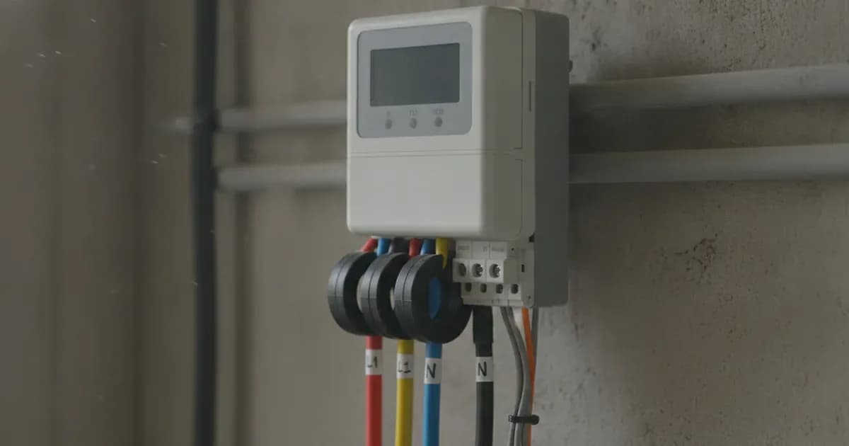
- CT clamp arrows must point towards household loads, away from the grid incomer.
- Zero export is configured in the SolarGo app by setting the maximum export limit to 0 Watts.
- Always ensure complete AC circuit isolation and lock-out before installing CT clamps on live busbars.
Understanding the GoodWe GM3000 Smart Meter
The GoodWe GM3000 is a three-phase smart meter designed to monitor energy flow in solar installations, particularly when paired with GoodWe ET inverters. Its primary function is to measure power consumption and generation, enabling features like export power limiting. This is crucial for compliance with grid regulations and for managing energy usage effectively.
The GM3000 communicates with the inverter using the RS485 Modbus RTU protocol. This allows the inverter to receive real-time data on energy flow, which it then uses to adjust its output. The meter is compatible with standard three-phase electrical distribution systems.
Wiring the GoodWe GM3000 Smart Meter
Correct wiring of the GoodWe GM3000 is essential for accurate measurement and reliable communication. The meter requires both communication wiring to the inverter and voltage sensing leads connected to the main AC supply.
RS485 Communication Wiring
Connect RS485 differential communication wires A and B from the smart meter to the Meter port on the inverter. This establishes the data link for export power limit control and energy monitoring. Maintain shielded twisted-pair cabling to ensure communication integrity and prevent interference. Verify proper RS485 communication baud rate settings between the meter and inverter.
Voltage Sensing Leads
In GoodWe three-phase systems, ensure GM3000 voltage sensing leads (L1, L2, L3, N) are wired directly to the main AC incoming terminals. These connections provide the meter with the necessary voltage reference for accurate power calculations across all three phases.
Installing Current Transformer (CT) Clamps
Current Transformer (CT) clamps measure the current flowing through your AC cables. Their correct installation and orientation are critical for the GM3000 to accurately determine power flow.
Step | Instruction | What to check |
|---|---|---|
1 | Isolate AC circuit | Ensure complete AC circuit isolation and lock-out before installing CT clamps on live busbars. This is a critical safety step to prevent electric shock. |
2 | Place CT clamps | Install Current Transformer clamps with arrows pointing towards the household loads away from the grid incomer. This ensures the meter correctly identifies the direction of power flow. |
3 | Check polarity | Negative power flow during high household consumption indicates inverted CT clamp installation. If this occurs, reverse the CT clamp on the cable. |
Configuring Export Power Limits
The GoodWe GM3000, in conjunction with your GoodWe ET inverter, allows you to set an Export Power Limit. This feature is often used to comply with grid connection agreements or to achieve "zero export," where no solar power is sent back to the grid.
To set a zero export limit:
- Access the SolarGo app.
- Navigate to the Export Power Limit settings.
- Enable the Export Power Limit function.
- Set the maximum export limit value to 0 Watts.
This configuration instructs the inverter to modulate its output so that no excess power is fed into the grid. The RS485 Modbus RTU protocol facilitates this real-time control between the meter and the inverter.
What you can check yourself, and what you cannot
Homeowners can typically monitor the system's performance via the SolarGo app and observe whether export limits are being respected. You can also visually inspect CT clamp orientation if it is safely accessible and the AC circuit is isolated. However, any physical wiring, including connecting RS485 wires, voltage sensing leads, or installing CT clamps on live busbars, must be performed by a qualified and accredited installer. Changing inverter settings that affect grid protection or connection agreements should also be done by a professional.
What the published sources do not tell you
While official documentation provides specific wiring and configuration instructions, it does not detail the exact physical terminal layout on the GM3000 or the inverter's Meter port beyond "A and B". It also does not specify the exact baud rate for RS485 communication, which may need to be verified in the inverter's settings. The precise steps within the SolarGo app interface can also vary with app updates, though the core function remains consistent. Grid connection requirements and specific export limits can vary by Distribution Network Operator (grid operator) in Great Britain, and these local rules are not covered by the general meter installation guide.
Add a battery at a surveyed price
Installers quote supply and fitting of the battery on this page for your existing or new system.
How this pays for the site: installers pay SolarNevs a fixed introduction fee when we pass them a genuine enquiry. They cannot pay to appear higher, and our surveyed prices are published before any introduction. You can also take our dated price tables straight to any installer.
Frequently asked questions
What are the primary technical requirements for goodwe gm3000 smart meter wiring and export power limit guide?
Key requirements include compliance with local grid codes, correct equipment certification, and proper electrical isolation.
Who is authorized to install and inspect goodwe gm3000 smart meter wiring and export power limit guide?
All high-voltage DC, AC grid tie-in, and switchboard modifications must be performed by a qualified, accredited electrical professional.
How is export power limited in goodwe gm3000 smart meter wiring and export power limit guide?
Export limiting is achieved using certified bidirectional smart meters or power sensors providing dynamic feedback to the inverter system.
References
- GoodWe official downloads for the Smart Meter GM1000/GM1000D/GM3000 series (quick installation guide, datasheet, declaration of conformity) — accessed 6 September 2026
- NEPRA (Alternative & Renewable Energy) Distributed Generation and Net Metering Regulations, 2015 — SRO 892(I)/2015 — accessed 6 September 2026
- NEPRA legislation index listing the Distributed Generation and Net Metering Regulations and their five amendments — accessed 6 September 2026
Related guides
More from what to buy — and how not to get cheated.