APsystems ECU Gateway and Consumption Metering Guide
Updated 6 September 2026 · By SolarNevs Research Desk, Dealer surveys + verified sources · 2 sources · Method ↗
Key Takeaways
- The APsystems ECU-C serves as the central telemetry and energy management gateway for microinverter arrays.
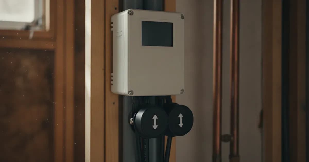
- It uses dual split-core Current Transformers (CTs) to monitor both solar production and household consumption.
- Zero Export functionality, enabled via the DTU management portal, dynamically throttles microinverter output to prevent grid export.
- CT clamps must be installed with their arrows pointing towards the household loads and away from the grid incomer.
- Installation requires strict adherence to AC circuit isolation and lock-out procedures to ensure safety.
APsystems ECU Gateway: Your Solar Energy Hub
The APsystems Energy Communication Unit (ECU) acts as the central control and monitoring point for your solar microinverter system. Specifically, the APsystems ECU-C is designed to provide detailed energy management capabilities. It functions as the central telemetry and energy management gateway for microinverter arrays, collecting critical performance data from each microinverter. This data is then transmitted to the EMA Cloud for real-time monitoring and diagnostics.
The ECU-C is compatible with standard single-phase and three-phase electrical distribution systems globally. It is engineered for residential and commercial off-grid and grid-parallel energy storage systems worldwide, offering a versatile solution for various solar installations.
How the ECU-C Measures Your Energy Flows
Accurate energy monitoring is crucial for understanding your solar system's performance and household consumption patterns. The ECU-C achieves this by utilizing split-core current transformers (CTs). These sensors are designed to measure aggregate solar generation and household power flows.
A typical setup involves two CT clamps:
- Production CT: Measures the electricity generated by your solar microinverters.
- Consumption CT: Measures the electricity flowing into or out of your property from the grid, allowing the ECU-C to calculate your net consumption or export.
These measurements provide a comprehensive view of your energy ecosystem, enabling informed decisions about energy usage and export management.
Setting Up Dynamic Zero Export Control
Many network operators and local regulations require solar installations to prevent or limit the export of electricity back to the grid. This is where the ECU-C's dynamic Zero Export feature becomes essential.
Zero Export is a function that dynamically throttles microinverter generation. This means your microinverters will adjust their output in real-time to match your household's consumption, ensuring that no excess solar power is sent to the grid. To activate this feature, you must enable Zero Export in the DTU management portal. This configuration helps you comply with local grid regulations and avoid potential penalties or charges for exporting power without an appropriate agreement.
Correct CT Clamp Installation and Wiring
Proper installation of the CT clamps is critical for accurate energy monitoring and the effective operation of Zero Export. Incorrect wiring or orientation can lead to inaccurate readings and system malfunctions.
Installation Steps and Safety
- Orientation: Install Current Transformer clamps with arrows pointing towards the household loads away from the grid incomer. This ensures that the ECU-C correctly interprets the direction of current flow for both production and consumption.
- Wiring Integrity: Maintain shielded twisted-pair cabling for the CT sensors. This helps prevent electrical interference and ensures reliable data transmission. Verify proper RS485 communication baud rate settings as per the manufacturer's instructions to ensure stable communication between the CTs and the ECU-C.
- Safe Panel Isolation Protocols: Before installing CT clamps on live busbars, ensure complete AC circuit isolation and lock-out. This is a critical safety measure to prevent electric shock. Always follow local electrical safety regulations and use appropriate personal protective equipment.
- Protective Bonding: Bond inverter chassis ground and battery metal enclosure to the main installation earthing terminal. This provides essential protective earthing for the system, enhancing safety and preventing electrical hazards.
Monitoring Your System with EMA Cloud
Once your APsystems ECU-C and CT clamps are correctly installed and configured, your system will begin sending data to the EMA Cloud. This real-time EMA Cloud telemetry allows you to monitor your solar production, household consumption, and grid interactions from anywhere.
The EMA Cloud platform provides diagnostic tools and performance insights, helping you track your energy savings and system health. While official scheme guidelines mentions the ESS assistant dynamically manages battery charge and discharge based on grid tariffs and load, the primary function for the ECU-C in this context is data collection and enabling the Zero Export function through the DTU portal, which then reflects in the EMA Cloud.
What You Can Check Yourself, and What You Cannot
As a homeowner, you can perform several basic checks to ensure your APsystems ECU-C system is operating correctly:
Maintenance Task | Homeowner Verification Scope | Accredited Installer Requirement |
|---|---|---|
CT Clamp Orientation | Visual inspection of load arrow direction | Physical clamping and un-clamping on live distribution busbars |
Telemetry & Reporting | Monitor production, consumption, and export in EMA Cloud | Gateway firmware updates and hardware fault diagnosis |
Communication Cabling | Inspect physical condition of external wiring | Terminating shielded twisted pairs and configuring RS485 baud rates |
Zero Export Control | Basic toggle in DTU management portal | Advanced grid-limitation parameter profiling |
Protective Earthing | Visual verification of external earth wire | Inverter chassis and enclosure bonding to main earthing terminal |
- Visual Inspection: Regularly check the physical condition of your CT clamps and their wiring for any visible damage or loose connections.
- EMA Cloud Data: Monitor your system's performance data through the EMA Cloud portal. Look for consistent production, consumption, and zero export behaviour.
- Arrow Orientation: If you suspect inaccurate readings, visually re-confirm that the CT clamp arrows are pointing towards the household loads away from the grid incomer.
However, certain tasks require the expertise of an accredited installer:
- Installation on Live Busbars: Any work involving the installation or removal of CT clamps on live busbars requires complete AC circuit isolation and lock-out, which should only be performed by a qualified electrician or accredited installer.
- RS485 Settings: Adjusting or troubleshooting RS485 communication baud rate settings should be left to a professional, as incorrect settings can disrupt data flow.
- System Configuration: While you can enable Zero Export in the DTU portal, any advanced configuration or troubleshooting of the ECU-C's internal settings should be handled by an APsystems-certified technician.
- Earthing Connections: Ensuring proper bonding of inverter chassis ground and battery metal enclosure to the main installation earthing terminal is a critical safety task for accredited professionals.
Attempting to perform tasks beyond your expertise can lead to electrical hazards, damage to equipment, or voiding of warranties.
What the published sources do not tell you
While the APsystems documentation provides clear guidance on the ECU-C's functionality and installation, specific details regarding local grid operator requirements for Zero Export may vary. Official scheme guidelines confirms that the ECU-C complies with international microgeneration safety and grid protection standards, but the exact export limits or specific connection agreements are determined by your local Distribution Network Operator (grid operator) in Great Britain. These are not universally published by APsystems.
Additionally, while official scheme guidelines mentions the ECU-C's compatibility with global electrical networks, it does not detail specific country-by-country installation nuances or regulatory differences beyond the general scope. Always consult your local grid operator and an accredited installer for site-specific requirements.
Add a battery at a surveyed price
Installers quote supply and fitting of the battery on this page for your existing or new system.
How this pays for the site: installers pay SolarNevs a fixed introduction fee when we pass them a genuine enquiry. They cannot pay to appear higher, and our surveyed prices are published before any introduction. You can also take our dated price tables straight to any installer.
Frequently asked questions
What is the APsystems ECU-C gateway?
The APsystems ECU-C acts as the central telemetry and energy management gateway for microinverter arrays, collecting data and enabling control functions.
How does the ECU-C measure energy consumption and production?
The ECU-C uses dual split-core current transformers (CTs) to measure both aggregate solar generation and household power flows, providing comprehensive energy monitoring.
What is Zero Export and how does the ECU-C enable it?
Zero Export is a function that dynamically throttles microinverter generation to prevent electricity export to the grid. You enable it in the DTU management portal.
How should CT clamps be oriented for the ECU-C?
Current Transformer clamps must be installed with their arrows pointing towards the household loads and away from the grid incomer for correct measurement.
What safety precautions are necessary when installing CT clamps?
Before installing CT clamps on live busbars, ensure complete AC circuit isolation and lock-out. Additionally, bond the inverter chassis ground to the main earthing terminal.
References
- APsystems ECU-C Communication Unit Manual — accessed 27 August 2026
- APsystems EMA App User Manual (energy monitoring) — accessed 27 August 2026
Related guides
More from what to buy — and how not to get cheated.