Inverter Shows Low Battery with Full Battery: Troubleshooting Guide
Updated 6 September 2026 · By SolarNevs Research Desk, Dealer surveys + verified sources · 5 sources · Method ↗
Key Takeaways
- The most common cause is a mismatch between the inverter's voltage settings and the battery's actual state.
- Always start by verifying the actual battery voltage directly at the terminals with a multimeter.
- Working with live DC circuits can be hazardous; always disconnect power and use insulated tools.
- For lithium batteries, BMS communication issues are a frequent cause of incorrect battery status readings.
- Stop DIY troubleshooting and call a qualified technician if you suspect internal inverter damage or cannot safely diagnose the issue.
Why does my inverter report a low battery when the battery is actually full?
When your inverter displays a low battery warning, but your battery bank appears to be fully charged, it indicates a discrepancy in how the inverter is sensing the battery's state. The most common causes are incorrect low DC cut-off settings in the inverter, voltage drop across the battery cables, or communication issues with a lithium battery's Battery Management System (BMS). The first step is to verify the actual battery voltage.
Diagnosis
Follow these steps to diagnose why your inverter is showing a low battery despite a full battery.
- Verify Actual Battery Voltage:
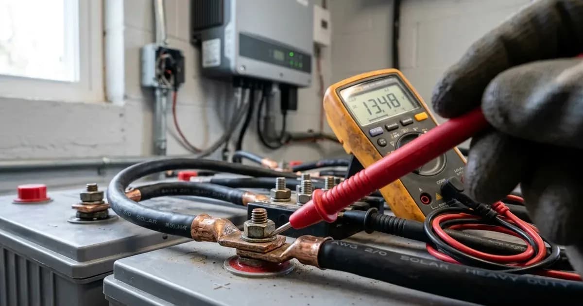
- Action: Turn off your inverter and disconnect all loads. Use a calibrated DC multimeter to measure the voltage directly across your battery bank's main terminals.
- Meaning:
- If the multimeter reading is significantly higher than the inverter's displayed voltage, there is a voltage sensing issue (e.g., cable drop or inverter calibration).
- If the multimeter reading is also low, then the battery is indeed low, and the inverter's reading is accurate. Proceed to troubleshoot why the battery is not charging or holding charge.
- For a Pylontech US3000C, if the battery cannot turn on and all lights are off or flashing, it may indicate the "Capacity too low, or module over discharged."
- Check Inverter Low DC Cut-off Settings:
- Action: Access your inverter's settings menu (e.g., Program 29 on Axpert VM III, Program 21 on Growatt SPF 5000 ES). Verify the "Low DC Cut-off Voltage" or equivalent setting.
- Meaning:
- If this setting is too high for your battery chemistry and state of charge, the inverter will prematurely shut down or warn of low battery. For example, an Axpert VM III 5KW inverter has a default low DC cut-off voltage of 42.0V. A Growatt SPF 5000 ES has a default low DC cut-off voltage of 42.0V.
- Ensure the setting aligns with your battery manufacturer's specifications.
- Inspect Battery Cables for Voltage Drop:
- Action: With the inverter running and under load, measure the voltage at the battery terminals and then at the inverter's DC input terminals.
- Meaning:
- A significant difference (more than a few tenths of a volt) indicates excessive voltage drop due to undersized cables, loose connections, or corrosion.
- For an Axpert VM III 5KW, the recommended battery cable size is 12AWG (38mm2). For a Growatt SPF 5000 ES, the recommended battery cable size is 12 AWG. Deye SG03LP1 5KW models recommend 3AWG (25mm2) cables. Pylontech US3000C batteries use two 4AWG power cables.
- Check BMS Communication (for Lithium Batteries):
- Action: For lithium battery systems, check the inverter's display for BMS communication error codes (e.g., "Warning code 33 BMS communication loss" on Growatt SPF 5000 ES, "F66 BMS communication fault" on Deye SG03LP1, "CAN Fail" on Solis S5-EH1P). Inspect the communication cable between the battery and the inverter.
- Meaning:
- A communication fault means the inverter cannot accurately read the battery's state of charge or voltage from the BMS, leading to incorrect warnings or shutdowns.
- The Pylontech US3000C communicates via RS485 and CAN. Solis S5-EH1P uses a CAN Port for communication with lithium battery BMS.
Cause/fix table
Symptom detail | Likely cause | Fix |
|---|---|---|
Inverter displays low battery, but multimeter shows battery is charged | Inverter's low DC cut-off voltage setting is too high | Adjust the inverter's low DC cut-off voltage setting to match battery specifications. For Axpert VM III 5KW, the range is 42.0V to 48.0V (Program 29). For Growatt SPF 5000 ES, the range is 40.0V to 48.0V (Program 21). |
Inverter displays low battery, and voltage at inverter terminals is low, but voltage at battery terminals is normal | Voltage drop across battery cables due to undersizing, loose connections, or corrosion | Inspect battery cables and terminals. Tighten all connections. Replace undersized cables with the manufacturer's recommended gauge. For Axpert VM III 5KW, use 12AWG (38mm2) cables. For Growatt SPF 5000 ES, use 12 AWG cables. Deye SG03LP1 5KW models recommend 3AWG (25mm2) cables. |
Inverter displays low battery, and lithium battery shows a communication error (e.g., F66, CAN Fail, Warning 33) | BMS communication failure between inverter and lithium battery | Check the communication cable (RS485/CAN) for secure connections and damage. Ensure the correct cable type is used. Verify inverter settings for BMS communication. If the Deye SG03LP1 displays F66, you can disable BMS_Err_Stop on the LCD as a temporary measure. |
Pylontech US3000C battery cannot turn on, no lights or flashing lights | Battery capacity too low or module over-discharged | Recharge the battery. The Pylontech US3000C requires recharging within 12 hours after being fully discharged. |
Pylontech US3000C battery turns on, but red light is on, and cannot charge or discharge | Low Voltage protection active (below 44.5V) | Recharge the battery. The Pylontech US3000C enters protection if voltage is 44.5V or less. |
Solis S5-EH1P displays "UN-Vbatt" | Battery undervoltage detected | Verify battery voltage is within standards. Measure battery voltage at inverter connection point. Contact your battery manufacturer for further service. |
Inverter and Battery Settings Checks
This section details specific settings to check on common inverter models and general considerations for battery types.
Inverter Low DC Cut-off and Warning Voltages
Inverters like the Axpert VM III and Growatt SPF 5000 ES have configurable low DC cut-off and warning voltages. These settings dictate when the inverter considers the battery "low" and takes action, such as shutting down or switching to grid power.
- Axpert VM III (48Vdc models like 5KW):
- Low DC Warning Voltage: 46.0Vdc (load < 50%), 44.0Vdc (load ≥ 50%)
- Low DC Cut-off Voltage: 43.0Vdc (load < 50%), 42.0Vdc (load ≥ 50%)
- These values can be adjusted in Program 29, with a range of 42.0V to 48.0V.
- Growatt SPF 5000 ES (48Vdc):
- Low DC Warning Voltage: 44.0Vdc (load < 50%), 40.4Vdc (load ≥ 50%)
- Low DC Cut-off Voltage: 42.0Vdc (load < 50%), 38.4Vdc (load ≥ 50%)
- These values can be adjusted in Program 21, with a range of 40.0V to 48.0V.
- For lithium batteries, Growatt SPF 5000 ES also uses State of Charge (SOC) settings: Low DC Cut-off SOC (5%~50%, default 20%) and Low DC Warning SOC (Low DC Cut-off SOC +5%).
- Deye SG03LP1 (40-60V battery range):
- For Li-ion batteries, the Deye SG03LP1 features self-adaption to the BMS. If a "F66 BMS communication fault" occurs, it indicates communication between the hybrid inverter and battery BMS is disconnected. You can disable the BMS_Err_Stop item on the LCD if you do not want this to happen.
- Solis S5-EH1P (42-58V battery range):
- If the inverter displays "UN-Vbatt" (Battery undervoltage detected), you should verify the battery voltage is within standards and measure the voltage at the inverter connection point. For Li-ion batteries, the OverDischg SOC can be set from 10% to 40% (default 20%).
Battery Cable Sizing
Inadequate battery cable sizing can lead to significant voltage drop, causing the inverter to sense a lower voltage than the battery's actual voltage, especially under heavy load.
- Axpert VM III:
- 1.5KW model: 1*6AWG (14mm2)
- 3KW model: 1*2AWG (38mm2)
- 5KW model: 1*2AWG (38mm2)
- Deye SG03LP1:
- 3.6/5Kw models: 3AWG (25mm2)
- 6Kw model: 2AWG (35mm2)
- Growatt SPF 5000 ES:
- SPF 3500 ES model: 1 * 4 AWG
- SPF 5000 ES model: 1 * 2 AWG
- Pylontech US3000C:
- Uses two 4AWG power cables, with a peak current capacity of 120A and constant 100A. Grounding cables should be 10AWG or higher.
For more detailed guidance on selecting the correct cable size for your solar system, you can refer to a solar cable sizing tool.
Lithium Battery BMS Communication
For lithium battery systems, the Battery Management System (BMS) plays a critical role in reporting the battery's status to the inverter. Communication failures can lead to inaccurate readings.
- Pylontech US3000C: Features built-in BMS with RS485 and CAN communication. It manages and monitors cells for voltage, current, and temperature.
- Growatt SPF 5000 ES: Supports CAN/RS485 for BMS communication. A "Warning code 33 BMS communication loss" indicates a problem.
- Deye SG03LP1: Has a BMS 485 Port and BMS CAN Port. An "F66 BMS communication fault" means communication between the hybrid inverter and battery BMS is disconnected.
- Solis S5-EH1P: Includes a CAN Port for communication with lithium battery BMS. A "CAN Fail" error indicates a communication failure.
Ensure all communication cables are securely connected and that the inverter's settings are configured for the correct BMS protocol (CAN or RS485).
Safety: Working with Batteries and Inverters
Working with solar power systems involves significant electrical and chemical hazards. Always prioritize safety.
- Disconnect Power: Before performing any inspections or adjustments, always disconnect all power sources to the inverter and battery bank. This includes AC input, PV input, and battery connections. For GoodWe ET inverters, wait at least 5 minutes after disconnection for capacitors to discharge.
- Insulated Tools: Use only insulated tools when working on or around batteries and electrical connections. A dropped metal tool can cause a spark or short circuit, leading to an explosion or severe burns.
- Eye Protection: Always wear appropriate eye protection, especially when working with lead-acid batteries, as they contain corrosive acid.
- Correct Polarity: Ensure positive (+) terminals are connected to positive (+) and negative (-) to negative (-). Reverse polarity connections can severely damage the inverter and battery.
- Grounding: Inverters should be connected to a permanent grounded wiring system.
- Lithium Battery Specifics: Lithium batteries have internal BMS protection. Do not attempt to bypass or modify the BMS. If a Pylontech US3000C battery experiences a high voltage (above 55.5V) or cell voltage higher than 4V, it will trigger a high voltage protection alarm (buzzer rings and all LEDs flash). If the battery is under permanent protection (single cell voltage higher than 4.2V or lower than 1.5V or temperature higher than 80 degrees), it will be unable to charge and discharge with a red LED on.
- Temperature: The surface temperature of some inverters, like the Solis S5-EH1P, can reach up to 75℃ (167°F) during operation. Avoid touching the inverter surface while it is running to prevent burns.
When to call a technician instead
While many issues can be resolved with careful DIY troubleshooting, some situations require professional intervention.
- Persistent Faults: If you have followed all troubleshooting steps and the inverter continues to show a low battery warning, or if other fault codes appear, it's time to call a qualified solar technician.
- Internal Damage: If you suspect internal damage to the inverter, such as a tripped internal fuse (Axpert VM III) or a "MOSFAIL" error on a Pylontech US3000C, do not attempt repairs yourself. Opening the inverter or battery can void warranties and pose serious safety risks.
- BMS Failure: If your lithium battery's BMS appears to be faulty (e.g., Pylontech US3000C showing "BMS failure" after switch On), contact the battery manufacturer or a certified technician.
- Uncertainty: If you are unsure about any step, or uncomfortable working with high-voltage DC systems, always consult a professional. Incorrect wiring or settings can lead to equipment damage, fire, or personal injury.
Still showing the fault? Book a technician
If the steps above did not clear it, tell us the inverter or battery and the exact code. We pass it to a technician who covers your city; visit charges are quoted before they come.
How this pays for the site: the technician or verifier pays SolarNevs a fixed introduction fee. Nobody pays to be recommended, and you are free to use our free guides instead.
Products mentioned
Frequently asked questions
Why does my inverter report a low battery when the battery is actually full?
This often indicates a discrepancy between the inverter's voltage reading and the battery's true state. Common causes include incorrect low DC cut-off settings, voltage drop across battery cables, or issues with BMS communication in lithium systems.
How can I accurately measure my battery's voltage?
Use a multimeter to measure the voltage directly at the battery terminals. Compare this reading to the voltage displayed on your inverter. Ensure all loads are disconnected for the most accurate reading.
What are typical low DC cut-off voltage settings for a 48V battery system?
For a 48V system, typical low DC cut-off settings can range from 42.0V to 48.0V for Axpert VM III 5KW models, and 40.0V to 48.0V for Growatt SPF 5000 ES models. These settings should align with your battery manufacturer's recommendations.
Can battery cable issues cause an inverter to show a low battery?
Yes, undersized or poorly connected battery cables can cause significant voltage drop, especially under load. This means the inverter senses a lower voltage than what is actually present at the battery terminals, triggering a low battery warning.
What should I do if my lithium battery's BMS communication fails?
If your inverter reports a BMS communication fault (e.g., F66 on Deye SG03LP1 or CAN Fail on Solis S5-EH1P), first check all communication cables for secure connections. Ensure you are using the correct cable type and that the inverter's settings for BMS communication are correctly configured.
References
- Axpert VM III Manual — accessed 23 August 2026
- Growatt SPF 3500-5000 Manual — accessed 23 August 2026
- Deye SUN 3.6-6K SG03LP1 Manual — accessed 23 August 2026
- Solis S5-EH1P Manual — accessed 23 August 2026
- Pylontech US3000C Manual — accessed 23 August 2026
Related guides
More from inverter errors & fixes.