Growatt SPF 5000 ES Error Codes: Troubleshooting and Fixes
Updated 6 September 2026 · By SolarNevs Research Desk, Dealer surveys + verified sources · 2 sources · Method ↗
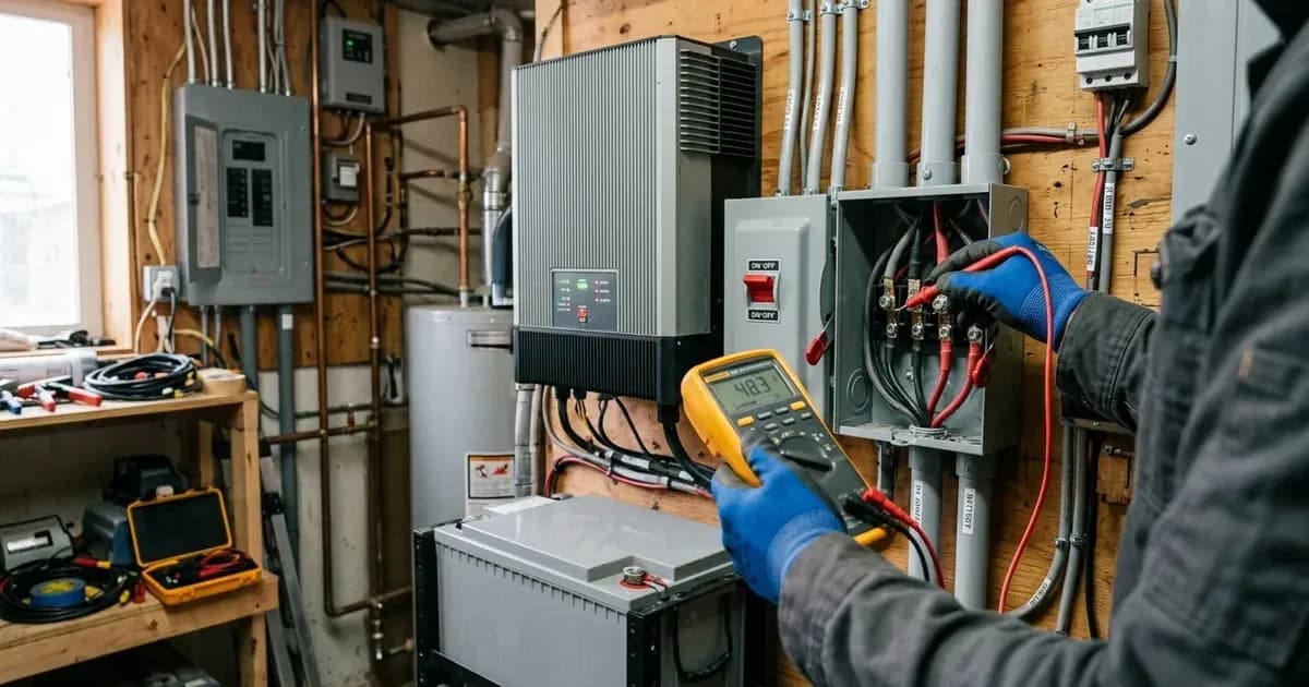
Growatt SPF ES series inverters are multifunctional off-grid solar inverters designed for backup power and self-consumption applications. When your Growatt SPF 5000 ES or SPF 3500 ES inverter displays an error or warning code, it indicates a specific operational issue that requires attention. Understanding these codes is crucial for maintaining system stability and preventing potential damage.
This guide provides a comprehensive diagnostic table for Growatt SPF ES inverters, differentiating between warning codes (which allow the unit to continue running) and fault codes (which typically shut down the inverter's output). We'll detail common issues like low battery voltage, high bus voltage, overcurrent, and low output voltage, along with instructions for setting up lithium battery communication.
Understanding Growatt SPF ES Error and Warning Codes
Growatt SPF ES inverters use a system of codes to communicate operational status and issues. These are broadly categorized into:
- Warning Codes: These indicate conditions that require attention but do not immediately shut down the inverter's output. The unit may continue to operate, but performance could be affected or a fault condition might be imminent.
- Fault Codes (Errors): These signify critical issues that cause the inverter to stop its output to protect itself or connected equipment. Addressing fault codes is essential to restore normal operation.
The inverter's display will show these codes, often accompanied by specific beeping patterns for warnings.
Detailed Troubleshooting for Common Growatt SPF ES Errors
Here's how to address some of the most frequently encountered fault and warning codes on your Growatt SPF ES inverter:
Error 04: Battery Voltage is Too Low
Meaning: This is a warning code indicating that the battery voltage or State of Charge (SOC) is too low. The inverter detects that the battery bank is discharged below acceptable levels.
Fix Direction:
- Measure Battery Voltage: Use a multimeter to measure the battery voltage at the DC input terminals of the inverter.
- Check Lithium Battery SOC: If using a lithium battery, check its SOC directly on the inverter's LCD display.
- Recharge the Battery: Ensure the battery bank is being recharged by solar or AC input. Verify that charging sources are active and correctly configured.
Error 08: Bus Voltage is Too High
Meaning: This fault code indicates that the internal DC bus voltage within the inverter has exceeded its safe operating limit.
Fix Direction:
- Check Lithium Battery Settings (without communication): If you are using a lithium battery without BMS communication, verify the voltage settings in Program 19 (C.V. charging voltage) and Program 21 (Low DC cut-off voltage). These values might be set too high for your specific lithium battery, leading to an overvoltage condition.
- Restart the Unit: Power down the inverter completely, wait a few minutes, and then restart it. If the error persists, contact a qualified service center.
Error 51: Over Current or Surge
Meaning: This fault code signifies that the inverter has detected an excessive current draw or a sudden power surge on its output. This often happens when connected loads exceed the inverter's capacity or during startup of inductive loads.
Fix Direction:
- Restart the Unit: Power cycle the inverter.
- Reduce Connected Load: If the error reoccurs, reduce the total load connected to the inverter by switching off some equipment.
- Contact Service Center: If the error persists after reducing the load and restarting, there may be an internal component failure, and the unit should be returned to a repair center.
Error 58: Output Voltage is Too Low
Meaning: This fault code indicates that the inverter's AC output voltage is lower than 80Vac. This can be caused by excessive load or an internal issue. This code is grouped with Fault code 06, which indicates output voltage too high (above 280Vac).
Fix Direction:
- Reduce Connected Load: Disconnect non-essential loads to see if the output voltage returns to normal.
- Restart the Unit: Power down and restart the inverter.
- Contact Service Center: If the error persists, the unit may require repair.
Comprehensive Growatt SPF ES Diagnostic Table
The following table lists all known error and warning codes for the Growatt SPF ES series inverters, along with their meanings and recommended fix directions.
Code | Type | Meaning | Fix Direction |
|---|---|---|---|
01 | Fault | Fan is locked | Check whether all fans are working properly. Replace the fan. |
02 | Fault | Internal temperature of component is over 100℃ | Check whether the air flow of the unit is blocked or whether the ambient temperature is too high. Check whether the thermistor plug is loose. |
03 | Fault | Battery is over-charged / Battery voltage is too high | Restart the unit. If the error happens again, return to repair center. Check if spec and quantity of batteries meet requirements. |
04 | Warning | The battery voltage/SOC is too low | Measure battery voltage in DC input. Check battery SOC in LCD when using Li battery. Recharge the battery. |
05 | Fault | Output short circuited | Check if wiring is connected well and remove abnormal load. |
06 | Fault | Output abnormal (Inverter voltage is higher than 280Vac) | Reduce the connected load. Restart the unit. If the error happens again, return to repair center. |
07 | Fault | The inverter is overload 110% and time is up | Reduce the connected load by switching off some equipment. |
08 | Fault | Bus voltage is too high | If you connect to a lithium battery without communication, check whether the voltage points of Program 19 and 21 are too high for the lithium battery. Restart the unit. If the error happens again, return to repair center. |
09 | Fault | Internal components failed (Bus soft start failed) | Restart the unit. If the error happens again, return to repair center. |
10 | Warning | Output power derating | Beep twice every 3 seconds. |
12 | Warning | Solar charger stops due to low battery | Beep once every second. |
13 | Warning | Solar charger stops due to high PV voltage | Beep once every second. |
14 | Warning | Solar charger stops due to overload | Beep once every second. |
15 | Warning | The input status is different in parallel system | Check if AC input wires of all inverters are connected well. |
16 | Warning | Input phase is not correct | Change the input phase S and T wiring. |
17 | Warning | The output phase not correct in parallel | Make sure the parallel settings are the same system (single or parallel; 3P1,3P2,3P3). Make sure all phases inverters are powered on. |
19 | Warning | Battery disconnect | No beep. |
20 | Warning | Li battery can't communicate to the inverter | Check whether communication line is correct connection between inverter and battery. Check whether BMS protocol type is correct setting. |
21 | Warning | PV power insufficient | Beep once every second. |
22 | Warning | Parallel forbidden without battery | Beep once every second. |
33 | Warning | BMS communication loss | Beep once every second. |
34 | Warning | Cell over voltage | Beep once every second. |
35 | Warning | Cell under voltage | Beep once every second. |
36 | Warning | Total over voltage | Beep once every second. |
37 | Warning | Total under voltage | Beep once every second. |
38 | Warning | Discharge over voltage | Beep once every second. |
39 | Warning | Charge over voltage | Beep once every second. |
40 | Warning | Discharge over temperature | Beep once every second. |
41 | Warning | Charge over temperature | Beep once every second. |
42 | Warning | Mosfet over temperature | Beep once every second. |
43 | Warning | Battery over temperature | Beep once every second. |
44 | Warning | Battery under temperature | Beep once every second. |
45 | Warning | System shut down | Beep once every second. |
51 | Fault | Over current or surge | Restart the unit. If the error happens again, return to repair center. |
52 | Fault | Bus voltage is too low | Restart the unit. If the error happens again, return to repair center. |
53 | Fault | Internal components failed (Inverter soft start failed) | Restart the unit. If the error happens again, return to repair center. |
55 | Fault | Over DC voltage in AC output | Restart the unit. If the error happens again, return to repair center. |
56 | Fault | Battery is not connected well or fuse is burnt | If you connect to a lithium battery without communication, check whether the voltage points of Program 19 and 21 are too high for the lithium battery. If the battery is connected well, restart the unit. If the error happens again, return to repair center. |
57 | Fault | Internal components failed (Current sensor failed) | Restart the unit. If the error happens again, return to repair center. |
58 | Fault | Output abnormal (Inverter voltage is lower than 80Vac) | Reduce the connected load. Restart the unit. If the error happens again, return to repair center. |
60 | Fault | Negative power fault | Check whether the AC output connected to the grid input. Check whether Program 8 settings are the same for all parallel inverters. Check whether the current sharing cables are connected well in the same parallel phases. Check whether all neutral wires of all parallel units are connected together. If problem still exists, contact repair center. |
61 | Fault | PV voltage is too high | (Implies PV input issue, check PV array voltage) |
62 | Fault | Internal communication error | (No specific fix direction provided, contact service) |
80 | Fault | CAN fault | Check whether the parallel communication cables are connected well. Check whether Program 23 settings are right for the parallel system. If problem still exists, contact repair center. |
81 | Fault | Host loss | (No specific fix direction provided, contact service) |
BMS Lithium Communication Setup
For optimal performance and safety with lithium batteries, it is highly recommended to establish communication between your Growatt SPF ES inverter and the battery's Battery Management System (BMS).
1. Select Battery Type
Navigate to Program 05: Battery type on your inverter's LCD panel.
- Select LI if your lithium battery supports BMS communication. This option is "only suitable when communicated with BMS".
- If your lithium battery does not have BMS communication, select User-Defined 2. This allows you to manually set charge and low DC cut-off voltages in Programs 19, 20, and 21. For User-Defined 2, it is "recommended to set to the same voltage in program 19 and 20 (full charging voltage point of lithium battery). The inverter will stop charging when the battery voltage reaches this setting."
2. Configure Communication Protocol
If you selected "LI" in Program 05, you need to configure the communication protocol in Program 36: Communication protocol.
- Choose an RS485 Protocol (Protocol 1-50) or CAN Protocol (Protocol 51-99) that matches your battery's BMS.
3. Connect BMS Communication Cable
The Growatt SPF ES inverter features a dedicated BMS communication port that supports both CAN and RS485 protocols. Ensure your communication cable is correctly wired according to the pin assignment:
Pin Number | BMS Port Assignment |
|---|---|
1 | RS485B |
2 | RS485A |
4 | CANH |
5 | CANL |
4. Set Low DC Cut-off SOC (for "LI" mode)
When "LI" is selected in Program 05, you can set the Low DC cut-off SOC in Program 21. The default is 20%, and it is settable from 5% to 50%.
Safety Precautions
Working with solar inverters and battery systems involves significant electrical hazards. Always prioritize safety.
- Qualified Personnel: All wiring and maintenance must be performed by a qualified person.
- Disconnect Power: To reduce the risk of electric shock, disconnect all wirings before attempting any maintenance or cleaning. Turning off the unit alone will not eliminate this risk.
- Battery Safety:
- Charge only deep-cycle lead-acid type rechargeable batteries and lithium batteries. Other types may burst.
- NEVER charge a frozen battery.
- Be very cautious when working with metal tools on or around batteries to avoid sparks or short circuits. A short circuit across a battery bank can cause an explosion.
- Grounding: This inverter must be connected to a permanent grounded wiring system. Comply with local requirements and regulations.
- Circuit Protection:
- Install a separate AC breaker between the inverter and the AC input power source. The recommended specification is 40A for the SPF 3500 ES and 50A for the SPF 5000 ES.
- Install a separate DC circuit breaker between the inverter and the PV modules.
- Avoid Short Circuits: NEVER cause AC output and DC input short circuited. Do NOT connect to the mains when DC input short circuits.
- Parallel Operation: If using multiple inverters in parallel, do not connect the current sharing cable between inverters that are in different phases, as this may damage the inverters. Ensure all inverters share the same battery bank; otherwise, they will enter fault mode.
By following these troubleshooting steps and safety guidelines, you can effectively diagnose and resolve common issues with your Growatt SPF ES inverter, ensuring reliable operation of your off-grid solar system.
Still showing the fault? Book a technician
If the steps above did not clear it, tell us the inverter or battery and the exact code. We pass it to a technician who covers your city; visit charges are quoted before they come.
How this pays for the site: the technician or verifier pays SolarNevs a fixed introduction fee. Nobody pays to be recommended, and you are free to use our free guides instead.
Frequently asked questions
How do I clear faults on growatt spf 5000 es error codes troubleshooting?
Isolate DC and AC power, wait 5 minutes for internal capacitors to discharge, verify connections, and restart the unit following manufacturer restart sequence.
Are these error codes universal across countries?
Hardware error codes and communication protocols are brand-global, but grid voltage and frequency trip thresholds are governed by regional standards.
References
- Growatt SPF 3500-5000 ES Operation Manual — accessed 27 August 2026
- Growatt Technical Support Service — accessed 27 August 2026
Related guides
More from inverter errors & fixes.