Homage Inverter Settings Guide for Pakistan
Updated 6 September 2026 · By SolarNevs Research Desk, Dealer surveys + verified sources · 3 sources · Method ↗
Key Takeaways
- Homage inverters use physical rear-panel DIP switches (classic Vertex, Hexa, Octa, Neon, Falcon, Axiom) or a digital LCD program menu (Bolt and TronDuo series) for configuration.
- Power Off First: Always power off the inverter and disconnect AC mains and battery power before adjusting physical DIP switches to prevent shock.
- Servicing Terminals Safety: When servicing or tightening battery terminals, always disconnect battery and AC mains and wait at least 5 minutes for internal capacitors to discharge. A spanner across terminals can short a battery bank that can deliver hundreds of amps, causing severe burns or explosion. Always verify battery polarity with a digital multimeter before bolting terminal lugs to prevent DC Reverse Polarity Destruction.
- Equalization Safety: Battery equalization on Program 30/31 deliberately drives flooded tubular cells into the hydrogen gassing region; perform equalization only in a well-ventilated space away from sparks and open flames.
- Menu Navigation Caution: On rebadged hybrid platforms, program numbering can vary across firmware revisions; always verify and match parameters by setting name rather than program index alone.
How do I configure my Homage inverter for optimal performance in Pakistan?
Homage inverters, designed for the Pakistani market, come with specific settings to manage grid fluctuations and battery types. The configuration method depends on your inverter model: classic standalone UPS units use physical DIP switches on the rear panel, while newer Bolt and TronDuo hybrid inverters use a digital LCD program menu. The most common cause of poor performance or battery issues is incorrect settings for your specific battery type and local grid conditions. The first step is to identify your inverter model and its corresponding setting method.
Setting up your Homage Inverter
Homage inverters are categorized into two main types, each with a distinct method for adjusting settings. Understanding which type you have is crucial before making any changes.
1. Classic Standalone UPS Models (DIP Switch Configuration)
Models such as the Vertex, Hexa, Octa, Neon, Falcon, Axiom, and Prime series typically feature a bank of physical DIP switches or rocker selectors on the rear panel. These models are often referred to as "settings-first hardware" because they do not include Wi-Fi monitoring.
Safety First: Before adjusting any physical DIP switches, always turn the inverter power OFF and disconnect both AC input and battery power. Failure to do so can result in electric shock or damage to the unit.
Here are the common DIP switch settings and their recommended values for typical Pakistani residential use:
DIP Switch # | Parameter Name | Switch Position: OFF / UP | Switch Position: ON / DOWN | Recommended Setting for Pakistani Homes |
|---|---|---|---|---|
Switch 1 | AC Input Voltage Range | Narrow Mode (UPS): 170 V–280 V AC (10 ms transfer time; for sensitive computers, TVs) | Wide Mode (Appliance): 90 V–280 V AC (20 ms transfer time; tolerates heavy WAPDA voltage drops) | Wide Mode (ON) for general residential homes with frequent low grid voltage (140 V–180 V). Set to Narrow only for dedicated desktop PC setups. |
Switch 2 | AC Charging Current | 10 A (Low Current): For small batteries (≤100 Ah–120 Ah) to prevent overheating | 20 A / 25 A (High Current): For large tubular batteries (150 Ah–250 Ah+) for faster recovery | 20 A/25 A (ON) for Phoenix TX-1800/2500, AGS TR-1800/2500, Osaka, Daewoo tubular batteries. Set to 10 A for standard 100 Ah car batteries. |
Switch 3 | Battery Chemistry Selection | Lead-Acid / Tubular: Bulk 14.4 V–14.8 V, Float 13.6 V–13.8 V (per 12 V block) | Sealed / AGM / Gel: Bulk 14.1 V–14.4 V, Float 13.5 V–13.6 V (per 12 V block) | Tubular (OFF) for all tall tubular and flooded unsealed batteries. Set to AGM (ON) for VRLA dry batteries. |
Switch 4 (Duo Models) | Charger Priority (Solar vs Utility) | Solar First: Solar PV charges battery first; WAPDA charges only if solar unavailable | Utility First / Dual: WAPDA grid and solar charge battery simultaneously | Solar First for off-grid solar cost savings; Dual (Simultaneous) during high load-shedding seasons. |
2. Bolt & TronDuo Hybrid Series (LCD Digital Program Menu)
The more modern Homage Bolt series (e.g., HBS-3217SCC, HBS-4017SCC, HBS-5617SCC, HBS-6017SCC, HBS-8017SCC) and TronDuo series (HTD-5013SCC) utilize a digital LCD display and push-buttons for configuration. These models often include Wi-Fi monitoring capabilities.
To enter configuration mode:
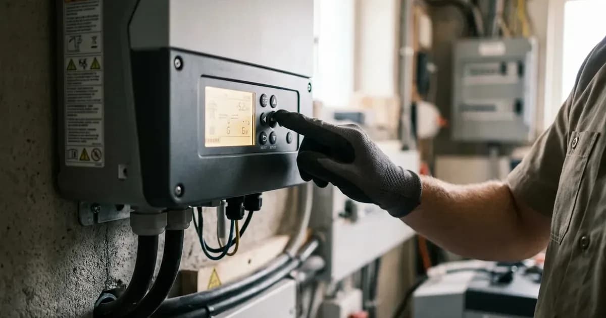
- Press and hold the ENTER button for 3 seconds until the program number flashes on the LCD.
- Use the UP and DOWN buttons to navigate through program numbers (from
01to36). - Press ENTER to select a parameter, use UP/DOWN to modify its value, and press ENTER again to confirm the change.
- Press ESC to exit the menu.
The following table outlines key program settings and their recommended values, especially for tubular batteries and common Pakistani grid conditions. For a deeper dive into battery-specific settings, refer to our guide on Homage battery pairing and tubular settings.
Prog # | Parameter Description | Selectable Options | Default Setting | Recommended Value for PK Grid & Tubular |
|---|---|---|---|---|
CRITICAL CAVEAT | Menu Numbering Variation on Rebadged Units | Match by Setting NAME, not solely Program Number | Program numbering can vary across specific Homage Bolt / TronDuo firmware revisions and hardware generations. | Installers and users must verify and match parameters by descriptive setting name (e.g., "Maximum Charging Current", "Floating Charging Voltage", "Low DC Cut-off Voltage") on the LCD display rather than relying exclusively on index numbers. |
01 | Output Source Priority | | | |
02 | Maximum Charging Current | 10 A to 120 A (in 10 A increments) | 60 A | 20 A–30 A for 200 Ah tubular bank; up to 120 A for Lithium. |
03 | AC Input Voltage Range | | | |
05 | Battery Chemistry Type | | | |
06 | Auto Restart on Overload | | | |
07 | Auto Restart on Over-Temp | | | |
11 | Maximum Utility AC Charge Current | 2 A, 10 A, 20 A, 30 A, 40 A, 50 A, 60 A, 80 A, 100 A | 30 A | 15 A–20 A for single 200 Ah battery; 40 A–60 A for parallel banks. |
12 | Voltage Point Back to Grid (SBU Mode) | 22.0 V–29.0 V (24 V) / 44.0 V–58.0 V (48 V); or 10%–90% SOC | 23.0 V (or SOC 30%) (24 V) / 46.0 V (or SOC 30%) (48 V) | 23.5 V (24 V) / 47.0 V (48 V) for Tubular. |
16 | Charger Source Priority | | | |
26 | Bulk / Absorption Charging Voltage | 25.0 V–31.5 V (24 V) / 48.0 V–61.0 V (48 V) | 28.2 V (24 V) (AGM) / 56.4 V (48 V) (AGM) | 29.2 V (24 V) at 25°C / 58.4 V (48 V) at 25°C (Required for deep-cycle tubular desulfation). |
27 | Floating Charging Voltage | 25.0 V–31.5 V (24 V) / 48.0 V–61.0 V (48 V) | 27.0 V (24 V) / 54.0 V (48 V) | Typical values for many tubular batteries are 27.4 V (24 V) at 25°C / 54.8 V (48 V) at 25°C. However, always consult your specific battery manufacturer's data sheet or our battery pairing table for the precise float voltage required to maintain optimal battery health without electrolyte dry-out. |
29 | Low DC Cut-off Voltage | 20.0 V–24.0 V (24 V) / 40.0 V–48.0 V (48 V) | 21.0 V (24 V) / 42.0 V (48 V) | For most tubular batteries, set this to 21.0 V (24 V) and 42.0 V (48 V) as recommended by manufacturers. These values are typically above the inverter's default to prevent deep sulfation. Always refer to your battery manufacturer's specifications or our battery pairing table for the precise low DC cut-off voltage. |
30 | Battery Equalization Enable | | | |
31 | Battery Equalization Voltage | 25.0 V–31.5 V (24 V) / 48.0 V–61.0 V (48 V) | 29.2 V (24 V) / 58.4 V (48 V) | Typical values for many tubular batteries are 30.0 V (24 V) at 25°C / 60.0 V (48 V) at 25°C. However, always consult your specific battery manufacturer's data sheet or our battery pairing table for the precise equalization voltage. |
Essential Settings for Battery Health
Properly configuring your inverter's battery settings is critical for the longevity and performance of your deep-cycle tubular batteries, which are commonly used in Pakistan.
The 0.10C Charging Current Rule
Always set the inverter charging current to approximately 10% of the battery's total Ampere-hour (Ah) rating. For example, a 200 Ah battery bank should have a charge current of 20 A. Charging at a rate greater than 0.20C (20% of Ah capacity) can lead to rapid electrolyte boiling, excessive water loss, and premature plate degradation.
Battery Voltage Settings
The Bulk/Absorption, Float, and Low DC Cut-off voltages are crucial. For tubular batteries, higher bulk and equalization voltages are often required to prevent sulfation and ensure full charge.
- Bulk/Absorption Voltage (Program 26): This is the primary charging voltage. For a 24 V tubular battery bank, a setting of 29.2 V at 25°C is recommended. For a 48 V bank, this should be 58.4 V at 25°C.
- Floating Charging Voltage (Program 27): Typical values for many tubular batteries are 27.4 V (24 V) at 25°C and 54.8 V (48 V) at 25°C. However, always consult your specific battery manufacturer's data sheet or our battery pairing table for the precise float voltage required to maintain optimal battery health without electrolyte dry-out.
- Low DC Cut-off Voltage (Program 29): This protects your battery from destructive deep discharge. For most tubular batteries, set this to 21.0 V (24 V) and 42.0 V (48 V) as recommended by manufacturers. These values are typically above the inverter's default to prevent deep sulfation. Always refer to your battery manufacturer's specifications or our battery pairing table for the precise low DC cut-off voltage.
Battery Equalization
Equalization is a controlled overcharge that helps balance cell voltages and remove sulfate crystals from battery plates, especially in flooded tubular batteries.
- Enable Equalization (Program 30): Set this to
EEN(Enable Equalization) for tubular batteries every 30–60 days; battery equalization drives cells into the hydrogen gassing region, requiring a well-ventilated space away from sparks and flames; keepEDS(Disabled) for AGM, Gel, and lithium batteries — equalization overcharge destroys sealed cells. - Equalization Voltage (Program 31): Typical values for many tubular batteries are 30.0 V (24 V) at 25°C / 60.0 V (48 V) at 25°C. However, always consult your specific battery manufacturer's data sheet or our battery pairing table for the precise equalization voltage. Equalization deliberately drives flooded cells into the hydrogen gassing region, creating an explosion hazard; ensure a well-ventilated space strictly away from sparks and open flames.
For specific battery brand recommendations, refer to our detailed guide on Homage battery pairing and tubular settings.
Hardware Connections and Monitoring
Proper physical connections are as important as software settings.
- AC Input / Output: Ensure heavy-duty screw terminals for Live (L), Neutral (N), and Ground (PE) are securely connected. The AC input must be protected by a dedicated 16 A/32 A double-pole circuit breaker.
- DC Battery Terminals: Heavy-gauge M6/M8 screw bolts with color-coded boots (Red for Positive
+, Black for Negative-). Minimum cable cross-sections: 16 mm² for 12 V 1000 W; 25 mm² for 24 V 2400 W; 35 mm² for 48 V 5000 W. When servicing or tightening battery terminals, always disconnect battery and AC mains and wait at least 5 minutes for internal capacitors to discharge. A spanner across terminals can short a battery bank that can deliver hundreds of amps, causing severe burns or explosion. Always verify battery polarity with a digital multimeter before bolting terminal lugs to prevent DC Reverse Polarity Destruction. - PV Solar Input (Duo & Bolt Models): MC4 or screw terminals with integrated reverse polarity protection are used. Always ensure your solar panel string voltage remains within the inverter's MPPT operating window.
For Bolt series hybrid inverters, you can monitor performance using SmartESS or WatchPower communication protocols, typically managed via associated mobile applications. Classic standalone inverters, however, rely entirely on the front-panel LED/LCD display and rear-panel DIP switches for status and configuration. If you are setting up Wi-Fi monitoring, you can find a detailed walkthrough in our inverter Wi-Fi monitoring setup guide.
Safety: Critical Warnings for Inverter Settings
Working with inverters and batteries involves significant electrical and chemical hazards. Always prioritize safety.
- Hydrogen Gas Hazard: Flooded tubular lead-acid batteries emit flammable hydrogen gas during bulk and equalization charging (>14.4 V per 12 V block). Batteries must be installed in a well-ventilated, shaded space strictly away from open flames, gas water heaters, or electrical switches that can produce sparks.
- High DC Bus Voltage: Internal high-voltage capacitors on Bolt and TronDuo series store up to 500 V DC even after turning the power switch off. Always disconnect battery and AC mains and wait at least 5 minutes for internal discharge before servicing.
- DC Reverse Polarity: Connecting battery cables in reverse (+ to -) instantly blows internal DC blade fuses and can rupture primary input MOSFETs. Always verify battery polarity with a digital multimeter before bolting terminal lugs.
- Battery Acid & PPE: Always wear eye protection safety glasses and rubber gloves when handling tubular batteries, especially when checking electrolyte levels or specific gravity with a hydrometer; hydrometer testing draws corrosive sulfuric acid from the cell. Top up cells with pure distilled water only, never acid. Neutralize acid spills immediately with baking soda and water.
When to call a technician instead
While many settings can be adjusted by homeowners, internal hardware faults require professional diagnosis:
- Internal Component Faults: If your Bolt hybrid inverter displays
Fault 08/Fault 09/Fault 53/Fault 57(Internal components failed),Fault 51(Over current or surge),Fault 56(Battery connection open or fuse burnt), orFault 06/Fault 58(Output voltage abnormal), power cycle once; if the code persists, return the unit for board repair. - Audible Alarm Failures: Classic standalone UPS models displaying rapid beeping (4x/sec) with zero output voltage indicate blown power-stage MOSFETs requiring bench replacement.
- Service Center Network: Official authorized service centers backed by R&I Electrical Appliances (Pvt) Ltd operate across Karachi, Lahore, Rawalpindi/Islamabad, Faisalabad, Multan, Gujranwala, Peshawar, Quetta, Hyderabad, and Sukkur, providing warranty repairs under the standard 1-Year to 2-Year official warranty.
For a full breakdown of diagnostic fault codes and buzzer alarm patterns, refer to our Homage inverter error codes list.
Still showing the fault? Book a technician
If the steps above did not clear it, tell us the inverter or battery and the exact code. We pass it to a technician who covers your city; visit charges are quoted before they come.
How this pays for the site: the technician or verifier pays SolarNevs a fixed introduction fee. Nobody pays to be recommended, and you are free to use our free guides instead.
Frequently asked questions
What is the difference between Narrow and Wide AC input modes on Homage inverters?
Narrow Mode (UPS) accepts 170 V–280 V AC for sensitive electronics. Wide Mode (Appliance) accepts 90 V–280 V AC, tolerating common low grid voltages in Pakistan, but with a slower transfer time.
How do I set the charging current for my Homage inverter?
For classic models, use DIP Switch 2 to select 10 A or 20 A/25 A. For Bolt/TronDuo models, adjust Program 02 (Maximum Charging Current) and Program 11 (Maximum Utility AC Charge Current) to match your battery's 0.10C rating.
Which battery chemistry setting should I use for tubular batteries with a Homage inverter?
For classic models, set DIP Switch 3 to 'Lead-Acid / Tubular' (OFF position). For Bolt/TronDuo models, select 'FLD' (Flooded/Tubular) in Program 05.
How do I access the digital program menu on Homage Bolt and TronDuo inverters?
Press and hold the ENTER button for 3 seconds until the program number flashes on the LCD. Use the UP and DOWN buttons to navigate, ENTER to select, and ESC to exit.
What is the recommended equalization voltage for tubular batteries with Homage inverters?
Typical values for many tubular batteries are 30.0 V (24 V) at 25°C and 60.0 V (48 V) at 25°C. However, always consult your specific battery manufacturer's data sheet or our battery pairing table for the precise equalization voltage. This setting is found in Program 31 on Bolt/TronDuo models and should be enabled in Program 30 (EEN). Battery equalization deliberately drives flooded tubular cells into the hydrogen gassing region, so ensure a well-ventilated space strictly away from sparks and open flames.
References
- Homage.pk Vertex Series Product Page — accessed 24 August 2026
- Voltronic Power Axpert VM IV Manual (OEM for Homage Bolt Series) — accessed 24 August 2026
- W11stop.com Homage UPS User Manual and Error Codes (Community Reported) — accessed 24 August 2026
Related guides
More from inverter errors & fixes.