Homage Battery Settings: Pairing Guide for Tubular Batteries
Updated 6 September 2026 · By SolarNevs Research Desk, Dealer surveys + verified sources · 5 sources · Method ↗
Key Takeaways
- Correctly setting your Homage inverter for tubular batteries prevents premature capacity loss, plate damage, and cell reversal.
- Homage inverters use either rear-panel DIP switches (classic models) or an LCD program menu (Bolt/TronDuo series) for battery settings.
- Always match the inverter's AC charging current to approximately 10% of your battery's Ampere-hour (Ah) rating (10 A for 100 Ah, 15 A – 20 A for 180 Ah – 200 Ah, 25 A – 30 A for 250 Ah+).
- Flooded tubular batteries require periodic equalization (every 30–60 days) to balance cells; because equalization deliberately drives cells into the explosive hydrogen gassing region, the battery bank must be located in an actively ventilated space away from sparks and open flames.
- Check electrolyte level indicators every 15–30 days during summer and top up with pure distilled water only (never add acid) while wearing safety glasses and rubber gloves; all voltage setpoints are referenced to 25°C.
How do I set up my Homage inverter for tubular batteries?
Setting up your Homage inverter for tubular batteries involves configuring specific charge voltages, currents, and battery type settings. This ensures your batteries charge correctly, maintain their capacity, and deliver optimal backup during Pakistani load-shedding cycles. The method for adjusting these settings depends on your Homage inverter model: classic standalone UPS units use physical DIP switches, while the Bolt and TronDuo hybrid series use an LCD digital program menu (Prog 01 to 36).
Homage Classic Inverter DIP Switch Settings for Tubular Batteries
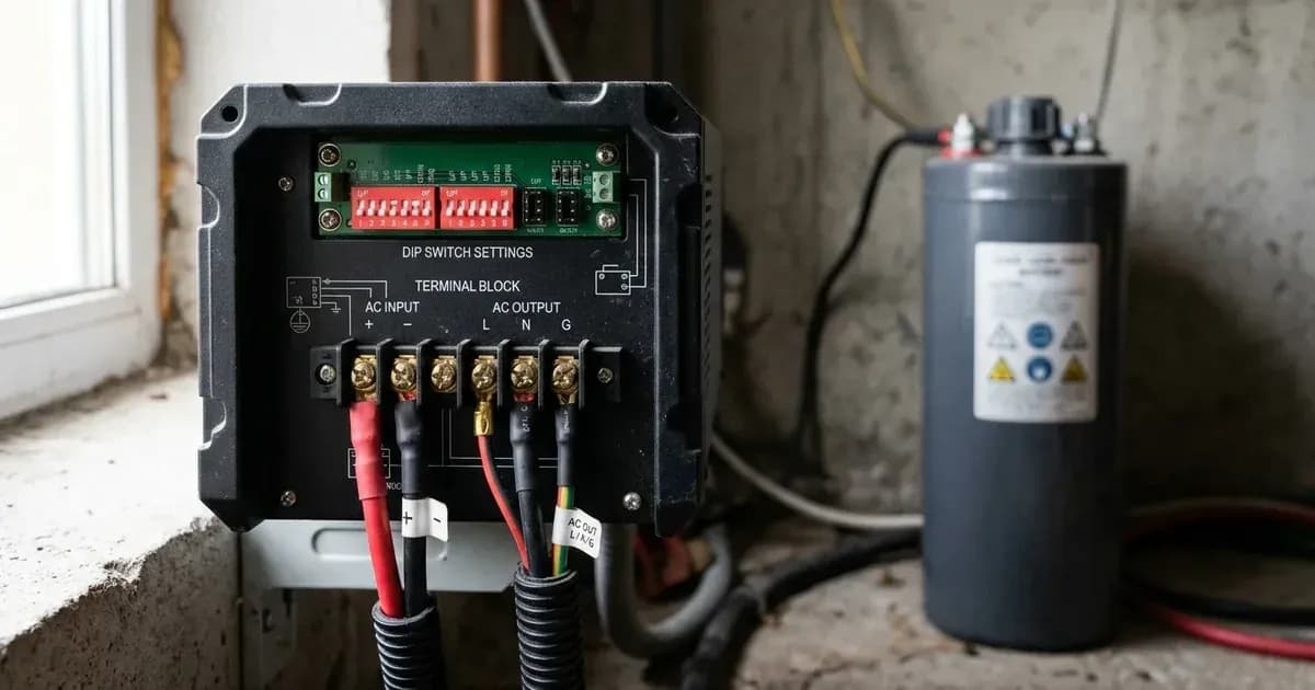
Classic Homage standalone UPS models, such as the Vertex (HVS-1214SCC, HVS-2414SCC), Hexa, Octa, Neon, Falcon, and Axiom series, feature physical DIP switches or rocker selectors on the rear panel for hardware configuration.
Always turn the inverter power OFF before adjusting physical DIP switches.
Here are the critical DIP switch settings for tubular batteries:
DIP Switch # | Parameter Name | Switch Position: OFF / UP | Switch Position: ON / DOWN | Recommended Setting for Pakistani Homes |
|---|---|---|---|---|
Switch 1 | AC Input Voltage Range | Narrow Mode (UPS): 170 V – 280 V AC (10 ms transfer time; for sensitive computers, TVs) | Wide Mode (Appliance): 90 V – 280 V AC (20 ms transfer time; tolerates heavy WAPDA voltage drops) | Wide Mode (ON) for general residential homes with frequent low grid voltage (140 V – 180 V). Set to Narrow only for dedicated desktop PC setups. |
Switch 2 | AC Charging Current | 10A (Low Current): For small batteries (≤100Ah–120Ah) to prevent overheating | 20A / 25A (High Current): For large tubular batteries (150Ah–250Ah+) for faster recovery | 20A/25A (ON) for Phoenix TX-1800/2500, AGS TR-1800/2500, Osaka, Daewoo tubular batteries. Set to 10A for standard 100Ah car batteries. |
Switch 3 | Battery Chemistry Selection | Lead-Acid / Tubular: Bulk 14.4 V – 14.8 V, Float 13.6 V – 13.8 V (per 12 V block) | Sealed / AGM / Gel: Bulk 14.1 V – 14.4 V, Float 13.5 V – 13.6 V (per 12 V block) | Tubular (OFF) for all tall tubular and flooded unsealed batteries. Set to AGM (ON) for VRLA dry batteries. |
For most tall tubular and flooded unsealed batteries, set DIP Switch 3 to the OFF / UP position for "Lead-Acid / Tubular". For larger batteries like Phoenix TX-1800/2500, AGS TR-1800/2500, Osaka, or Daewoo tubular batteries, set DIP Switch 2 to ON / DOWN for 20 A / 25 A charging. If you have a standard 100 Ah car battery, set DIP Switch 2 to OFF / UP for 10 A.
Homage Bolt Series LCD Program Settings for Tubular Batteries
Homage Bolt (HBS-3217SCC, HBS-4017SCC, HBS-5617SCC, HBS-6017SCC, HBS-8017SCC) and TronDuo (HTD-5013SCC) hybrid inverters, built on the Voltronic Power OEM platform, use an LCD digital program menu for detailed battery settings.
To access the configuration menu:
- Press and hold the ENTER button for 3 seconds until the program number flashes on the LCD.
- Use the UP and DOWN buttons to navigate through program numbers (
01to36). - Press ENTER to select parameter, UP/DOWN to modify, and ENTER to confirm. Press ESC to exit.
Here are the key program settings for tubular batteries:
Prog # | Parameter Description | Selectable Options | Default Setting | Recommended Value for PK Grid & Tubular |
|---|---|---|---|---|
CRITICAL CAVEAT | Menu Numbering Variation on Rebadged Units | Match by Setting NAME, not solely Program Number | Program numbering can vary across specific Homage Bolt / TronDuo firmware revisions and hardware generations. | Installers and users must verify and match parameters by descriptive setting name (e.g., "Maximum Charging Current", "Floating Charging Voltage", "Low DC Cut-off Voltage") on the LCD display rather than relying exclusively on index numbers. |
05 | Battery Chemistry Type | | | |
11 | Maximum Utility AC Charge Current | 2A, 10A, 20A, 30A, 40A, 50A, 60A, 80A, 100A | 30 A | 15A–20A for a single 200Ah battery; for larger parallel banks, size at approximately 10% of the total bank Ah rating (the 0.10 C rule). |
26 | Bulk / Absorption Charging Voltage | 25.0–31.5 V (24 V) / 48.0–61.0 V (48 V) | 28.2 V (24 V) / 56.4 V (48 V) | 29.2 V (24 V) / 58.4 V (48 V) (Required for deep-cycle tubular desulfation; 25°C reference). |
27 | Floating Charging Voltage | 25.0–31.5 V (24 V) / 48.0–61.0 V (48 V) | 27.0 V (24 V) / 54.0 V (48 V) | Default 27.0 V (24 V) / 54.0 V (48 V). |
29 | Low DC Cut-off Voltage | 20.0–24.0 V (24 V) / 40.0–48.0 V (48 V) in 0.1 V increments | 21.0 V (24 V) / 42.0 V (48 V) | Default 21.0 V (24 V) / 42.0 V (48 V); set 22.0 V (24 V) / 44.0 V (48 V) for tubular to prevent deep sulfation (25°C reference). |
30 | Battery Equalization Enable | | | |
31 | Battery Equalization Voltage | 25.0–31.5 V (24 V) / 48.0–61.0 V (48 V) | 29.2 V (24 V) / 58.4 V (48 V) | 30.0 V (24 V) / 60.0 V (48 V) (15.0 V per 12 V block; referenced to 25°C; drives cells into explosive hydrogen gassing region, requiring ventilated space away from sparks and flames). |
For example, if you have a 24 V system with Phoenix TX-2500 batteries, you would set Program 05 to FLD, Prog 26 to 29.2 V, Prog 27 to 27.0 V, and Prog 29 to 22.0 V (referenced to 25°C). You would also enable equalization (Program 30 to EEN) and set the equalization voltage (Prog 31) to 30.0 V. Because equalization deliberately drives cells into the explosive hydrogen gassing region, the battery bank must be located in an actively ventilated space away from sparks and open flames.
Inverter-Side Battery Pairing Specifications
The following table consolidates installer-standard pairing parameters for Pakistani tubular batteries with Homage inverters:
Battery Brand & Model | Chemistry & Nominal Capacity | Recommended Inverter System Voltage | Homage DIP Switch / Program 05 Setting | Max AC Charge Current Setting (Prog 11 / DIP Sw 2) | Bulk / Absorption Voltage (Prog 26) | Float Voltage (Prog 27) | Low DC Cutoff Voltage (Prog 29) | Equalization Voltage (Prog 31) |
|---|---|---|---|---|---|---|---|---|
Phoenix Tubular TX-1000 | Tall Tubular Flooded (100Ah @ C20) | 12 V DC (1x 12 V) | Tubular / | 10A (DIP Sw 2 OFF / Prog 11: 10A) | 14.6 V DC | 13.7 V DC | 10.5 V DC | 15.0 V DC (every 30 days) |
Phoenix Tubular TX-1800 | Tall Tubular Flooded (180Ah @ C20) | 12 V or 24 V (1x or 2x 12 V) | Tubular / | 20A / 25A (DIP Sw 2 ON / Prog 11: 20A–25A) | 14.6 V (12 V) / 29.2 V (24 V) | 13.7 V (12 V) / 27.4 V (24 V) | 10.5 V (12 V) / 21.0 V (24 V) | 15.0 V (12 V) / 30.0 V (24 V) |
Phoenix Tubular TX-2500 / TX-3000 | Tall Tubular Flooded (230Ah–250Ah) | 24 V or 48 V (2x or 4x 12 V) | Tubular / | 25A–30A (Prog 11: 25A–30A) | 29.2 V (24 V) / 58.4 V (48 V) | 27.4 V (24 V) / 54.8 V (48 V) | 21.0 V (24 V) / 42.0 V (48 V) | 30.0 V (24 V) / 60.0 V (48 V) |
AGS Tubular TR-1000 | Flooded Deep Cycle (105Ah @ C20) | 12 V DC (1x 12 V) | Tubular / | 10A (DIP Sw 2 OFF / Prog 11: 10A) | 14.6 V DC | 13.7 V DC | 10.5 V DC | 15.0 V DC |
AGS Tubular TR-1800 | Tall Tubular Deep Cycle (175Ah @ C20) | 12 V or 24 V (1x or 2x 12 V) | Tubular / | 20A / 25A (DIP Sw 2 ON / Prog 11: 20A–25A) | 14.6 V (12 V) / 29.2 V (24 V) | 13.7 V (12 V) / 27.4 V (24 V) | 10.5 V (12 V) / 21.0 V (24 V) | 15.0 V (12 V) / 30.0 V (24 V) |
AGS Tubular TR-2500 | Tall Tubular Deep Cycle (230Ah @ C20) | 24 V or 48 V (2x or 4x 12 V) | Tubular / | 25A–30A (Prog 11: 25A–30A) | 29.2 V (24 V) / 58.4 V (48 V) | 27.4 V (24 V) / 54.8 V (48 V) | 21.0 V (24 V) / 42.0 V (48 V) | 30.0 V (24 V) / 60.0 V (48 V) |
Osaka Tubular 1800 / 2500 | Tall Tubular Flooded (180Ah–230Ah) | 12 V, 24 V, or 48 V | Tubular / | 20A–30A | 14.6 V (12 V) / 29.2 V (24 V) | 13.7 V (12 V) / 27.4 V (24 V) | 10.5 V (12 V) / 21.0 V (24 V) | 15.0 V (12 V) / 30.0 V (24 V) |
Daewoo DTT-195 / DTT-225 / DTT-245 | Maintenance-Free / Low-Maint Tubular | 12 V, 24 V, or 48 V | Tubular / | 20A–30A | 14.6 V (12 V) / 29.2 V (24 V) | 13.6 V (12 V) / 27.2 V (24 V) | 10.5 V (12 V) / 21.0 V (24 V) | 14.8 V (12 V) / 29.6 V (24 V) |
Volta Tubular T-1800 / T-2500 | Tall Tubular Flooded (175Ah–240Ah) | 12 V, 24 V, or 48 V | Tubular / | 20A–30A | 14.6 V (12 V) / 29.2 V (24 V) | 13.7 V (12 V) / 27.4 V (24 V) | 10.5 V (12 V) / 21.0 V (24 V) | 15.0 V (12 V) / 30.0 V (24 V) |
Exide Tubular TR-1800 / TR-2500 | Tall Tubular Flooded (180Ah–240Ah) | 12 V, 24 V, or 48 V | Tubular / | 20A–30A | 14.6 V (12 V) / 29.2 V (24 V) | 13.7 V (12 V) / 27.4 V (24 V) | 10.5 V (12 V) / 21.0 V (24 V) | 15.0 V (12 V) / 30.0 V (24 V) |
Standard Automotive Lead-Acid (AGS/Osaka 100Ah) | SLI Flooded Automotive (100Ah) | 12V DC (1x 12V) | Sealed / | 10A (Never use 20A on thin SLI plates) | 14.2V DC | 13.6V DC | 10.8V DC | Disabled |
Lithium LFP Battery (Narada / Pylontech / Dyness 48V) | LiFePO4 Lithium (100Ah 48V) | 48V DC (Bolt Series HBS) | | 50A (Max 100A) | Custom (Consult battery manufacturer's specifications) | 54.0V DC | 44.0V DC (15% SOC) | Disabled |
All voltage figures in the table above are referenced to 25°C. Equalization deliberately drives cells into the explosive hydrogen gassing region, requiring an actively ventilated space away from sparks and open flames.
Matching Charge Current to Your Tubular Battery Capacity
The charging current setting is crucial for the health and longevity of your tubular batteries. Always follow The 0.10 C Rule: set the inverter charging current to approximately 10% of the battery total Ampere-hour (Ah) rating.
For example:
- For a 100 Ah battery (Phoenix Tubular TX-1000 or AGS Tubular TR-1000), set the charge current to 10 A (DIP Sw 2 OFF / Prog 11: 10A).
- For a 180 Ah – 200 Ah battery (Phoenix Tubular TX-1800 or AGS Tubular TR-1800), set the charge current to 15 A to 20 A (DIP Sw 2 ON / Prog 11: 15A–20A).
- For a 230 Ah – 250 Ah+ battery (Phoenix Tubular TX-2500/3000 or AGS Tubular TR-2500), set the charge current to 25 A – 30 A (Prog 11: 25A–30A).
Charging at >0.20 C causes rapid electrolyte boiling, water loss, and plate warping, significantly shortening battery life.
Tubular Battery Maintenance for Homage Inverter Systems
Proper maintenance is essential for tubular batteries paired with Homage inverters to prevent capacity degradation and premature cell failure:
- Electrolyte Top-Up Schedule: Check electrolyte level indicators every 15–30 days during summer. Top up with pure distilled water only when the red float indicator drops below the green zone. Never add acid. Always wear safety glasses and rubber gloves when performing electrolyte top-ups.
- Specific Gravity Checks: Use an optical or hydrometer tester across all 6 cells per 12 V block. Full charge specific gravity must read 1.240 to 1.280 S.G. at 25°C. A reading below 1.200 S.G. with float voltage indicates severe cell stratification requiring manual equalization (Program 30/31). Always consult your inverter's manual and warranty terms before attempting advanced procedures, as improper handling may void your warranty or cause injury. Because equalization deliberately drives cells into the explosive hydrogen gassing region, the battery bank must be located in an actively ventilated space away from sparks and open flames, and technicians must wear safety glasses and rubber gloves. For detailed cell gravity balancing, see our guide on Phoenix battery low gravity troubleshooting.
- Terminal Protection: Clean white lead sulfate buildup using warm water and baking soda. Apply a thin coat of petroleum jelly or terminal grease to prevent terminal overheating and high-resistance voltage drops. When tightening, cleaning, or disconnecting DC battery terminals, always kill power first and use insulated tools; a spanner across a battery bank shorts hundreds of amps and can cause severe flash burns or fire. Minimum cable cross-section: 16 mm² for 12 V 1000 W; 25 mm² for 24 V 2400 W; 35 mm² for 48 V 5000 W.
- DC Reverse Polarity Destruction: Connecting the battery cables in reverse (+ to -) instantly blows the internal DC blade fuses and can rupture the primary input MOSFETs. Always verify battery polarity with a digital multimeter before bolting terminal lugs.
- High DC Bus Voltage Shock Hazard: Internal high-voltage capacitors on Bolt and TronDuo series store up to 500 V DC even after turning the power switch off. Always disconnect battery and AC mains and wait at least 5 minutes for internal discharge before servicing.
- Equalization: For Homage Bolt series inverters, enable equalization (Program 30 to
EEN) and set the equalization voltage (Prog 31) to 30.0 V (24 V) / 60.0 V (48 V), which is 15.0 V per 12 V block (referenced to 25°C). Equalization deliberately drives cells into the explosive hydrogen gassing region, which is hazardous; ensure the battery is in an actively ventilated space away from sparks and open flames, and wear safety glasses and rubber gloves. Always consult your inverter's manual and warranty terms before attempting advanced procedures, as improper handling may void your warranty or cause injury. For routine scheduling, follow our tubular battery maintenance schedule.
Safety Considerations for Tubular Battery Systems
Working with flooded tubular lead-acid batteries and Homage inverters requires strict adherence to safety protocols:
- Explosive Hydrogen Gas Hazard: Flooded tubular lead-acid batteries emit flammable hydrogen gas during bulk and equalization charging (>14.4 V / cell at 25°C reference temperature). Batteries must be installed in a well-ventilated, shaded space away from gas water heaters, open flames, or electrical switches that can produce sparks.
- Battery Acid Corrosion & PPE: Always wear safety glasses and rubber gloves when checking tubular electrolyte specific gravity with a hydrometer or topping up distilled water. Neutralize acid spills immediately with baking soda and water. Add pure distilled water only, never acid.
- DC Terminal Work & Short-Circuit Risk: When bolting, tightening, or disconnecting battery cables, always kill power first and use insulated tools; a spanner across a battery bank shorts hundreds of amps and can cause severe flash burns or fire. Minimum cable cross-section: 16 mm² for 12 V 1000 W; 25 mm² for 24 V 2400 W; 35 mm² for 48 V 5000 W.
- DC Reverse Polarity Destruction: Connecting the battery cables in reverse (+ to -) instantly blows the internal DC blade fuses and can rupture the primary input MOSFETs. Always verify battery polarity with a digital multimeter before bolting terminal lugs.
- High DC Bus Voltage Shock Hazard: Internal high-voltage capacitors on Bolt and TronDuo series store up to 500 V DC even after turning the power switch off. Always disconnect battery and AC mains and wait at least 5 minutes for internal discharge before servicing.
When to call a technician instead
While basic parameter configuration and electrolyte maintenance can be managed by the system owner, certain faults require professional diagnosis:
- Your Homage inverter displays persistent fault codes related to internal component failure (Fault 08/09/53/57 on Bolt series).
- The inverter fails to power on or initiate charging despite correct DIP switch / LCD program settings and healthy battery open-circuit voltage.
- You suspect internal motherboard damage, such as blown internal DC blade fuses (40 A / 80 A) or shorted power MOSFETs following a lightning surge or reverse polarity connection.
- Your inverter is still covered under its standard 1-Year to 2-Year official repair/replacement warranty from the R&I Electrical Appliances / Kenwood authorized service network.
- You observe abnormal battery conditions such as excessive bubbling, bulging casings, or rapid water loss, as detailed in our guide on Osaka battery water loss and overcharging.
Still showing the fault? Book a technician
If the steps above did not clear it, tell us the inverter or battery and the exact code. We pass it to a technician who covers your city; visit charges are quoted before they come.
How this pays for the site: the technician or verifier pays SolarNevs a fixed introduction fee. Nobody pays to be recommended, and you are free to use our free guides instead.
Products mentioned
Frequently asked questions
What is the recommended Bulk/Absorption voltage for a 24V tubular battery bank with a Homage inverter?
For a 24 V tubular battery bank, the recommended Bulk/Absorption voltage is 29.2 V DC (referenced to 25°C), which is required for deep-cycle tubular charging and desulfation. High-voltage charging and desulfation deliberately drive cells into the explosive hydrogen gassing region, requiring an actively ventilated space away from sparks and open flames. Always consult your inverter's manual and warranty terms before attempting advanced procedures, as improper handling may void your warranty or cause injury.
How often should I equalize my tubular batteries with a Homage inverter?
Homage inverters, particularly the Bolt series, allow equalization to be enabled (Program 30: `EEN`). For tubular batteries, equalization is mandatory every 30–60 days at 30.0 V for 24 V (referenced to 25°C) to balance cells. Equalization deliberately drives the cell into the explosive hydrogen gassing region; ensure the battery is in a well-ventilated space away from sparks and open flames, and wear safety glasses and rubber gloves. Always consult your inverter's manual and warranty terms before attempting advanced procedures, as improper handling may void your warranty or cause injury.
What is the correct charge current for a 200Ah tubular battery connected to a Homage inverter?
The charging current should be approximately 10% of the battery's total Ampere-hour (Ah) rating (the 0.10 C rule). For a 200 Ah tubular battery, a setting of 15 A to 20 A is recommended on Homage inverters (DIP Switch 2 ON or Prog 11: 15A–20A). Always turn the inverter power OFF before adjusting physical DIP switches.
Can I use the 'Sealed / AGM / Gel' setting for my tubular batteries on a Homage inverter?
No, for tall tubular and flooded unsealed batteries, you must select the 'Lead-Acid / Tubular' DIP switch setting (OFF) or 'FLD' in Program 05. Using the AGM setting can lead to undercharging and premature battery degradation. Always turn the inverter power OFF before adjusting physical DIP switches.
What is the low DC cutoff voltage for a 48V tubular battery bank on a Homage inverter?
The factory default is 42.0 V DC; for a 48 V tubular bank set the Low DC Cut-off (Prog 29) to 44.0 V DC to prevent deep sulfation (referenced to 25°C).
References
- Homage Official Website — accessed 24 August 2026
- Voltronic Power OEM Downloads — accessed 24 August 2026
- Homage Vertex HVS-1214SCC Product Page — accessed 24 August 2026
- W11Stop Retailer - Homage UPS Specifications — accessed 24 August 2026
- W11Stop Retailer - Homage Bolt Series Specifications — accessed 24 August 2026
Related guides
More from inverter errors & fixes.