Phoenix Battery Not Charging? Low Backup Fixes for Tubular Batteries
Updated 7 September 2026 · By SolarNevs Research Desk, Dealer surveys + verified sources · 9 sources · Method ↗
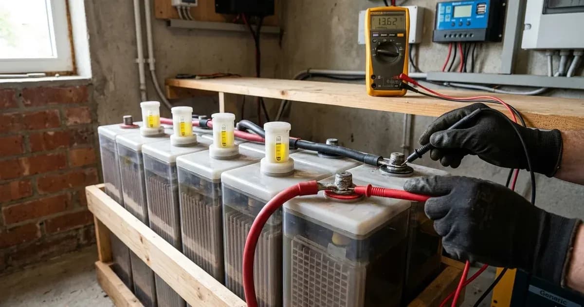
Phoenix Power Cube TX series deep-cycle tubular batteries (manufactured by Century Engineering Industries in Karachi, established 2005) are flooded tall-tubular lead-acid batteries widely installed across Pakistan for solar and UPS energy storage. Popular models include the 12 V 185 Ah (2.22 kWh) TX-1800 (5 plates per cell, 510×190×412 mm, 56 kg) and the 12 V 230 Ah (2.76 kWh) TX-2500 (7 plates per cell, ~63 kg). Century Engineering also produces other tubular units (such as TX-600 and TX-3000) alongside lithium storage systems (RLC-1.3-X1 to RLW-5.4-X1 from 1.3 to 5.37 kWh).
Because Phoenix publishes no official TX-series technical datasheet, charge-voltage specification, or published price list, owners and solar installers must rely on established flooded tubular battery standards and comparable manufacturer documentation (such as Osaka OPzS technical data, Rolls Battery engineering guidelines, and EnerSys manuals). When a Phoenix tubular bank fails to charge or provides prematurely short backup during load shedding, the issue typically stems from mismatched inverter voltage parameters, severe sulfation, electrolyte depletion, or cabling faults rather than an immediate internal cell defect.
Key Takeaways
- The primary cause of low backup in Phoenix tubular batteries is inverter undercharging from default AGM profile settings (56.4 V bulk on a 48 V bank); switch to Flooded (58.4 V bulk [14.6]), noting that charge setpoints are 25°C reference figures requiring -3 to -5 mV/cell/°C above 25°C temperature compensation in ambient heat.
- Inspect electrolyte levels wearing eye protection (adding distilled water only, never acid), and verify cell specific gravity with a hydrometer wearing eye protection (as it draws sulfuric acid out of the cell), targeting 1.260 at 25°C for a 100% full charge (Osaka OPzS benchmark).
- Flooded lead-acid batteries emit explosive hydrogen gas during charging; ensure continuous active room cross-ventilation and keep the battery bank strictly away from sparks and flames.
- Equalization (15.3 to 15.9 V per 12 V unit, or 2.55 to 2.65 V/cell; referenced to 25°C with -3 to -5 mV/cell/°C temperature compensation in ambient heat) deliberately drives cells into the hydrogen gassing region and requires active room ventilation away from sparks; perform it only after a full charge when cell specific gravity spread exceeds 0.030 across cells.
Common Symptoms & Quick Diagnosis Matrix
Use this diagnostic matrix to quickly identify whether your Phoenix battery fault originates from inverter configuration, wiring faults, or physical cell degradation:
Symptom / Observed Behavior | Likely Root Cause | Diagnostic Check | Immediate Fix / Action |
|---|---|---|---|
Inverter displays normal AC/solar input, but battery never charges on cloudy days | Charger source priority set to "Only Solar" (OSO) or grid charge disabled | Check inverter charger source priority setting (such as OSO, CSO, or SNU) | Change charger source priority to Solar First (CSO) or Solar and Utility (SNU) |
Zero charging current (0 A) on inverter display despite low state of charge | Blown DC fuse, loose or corroded terminal clamp, or charging disabled in inverter | Measure voltage at battery posts vs. inverter DC terminals with a multimeter | Kill power, clean posts, tighten clamps securely using insulated tools, and replace blown DC fuses |
Inverter switches to float early; battery voltage drops rapidly once load shedding starts | Inverter set to AGM/Gel (56.4 V) instead of Flooded (58.4 V); chronic deficit charging | Review inverter Program 05 chemistry mode and bulk voltage target | Set chemistry to Flooded (FLD) or configure User-Defined bulk to 58.4 V on 48 V bank [14.6] |
Short backup time (15–30 min) despite full charge voltage display | Severe plate sulfation from extended partial-state-of-charge operation | Measure per-cell specific gravity with a hydrometer wearing eye protection | Perform a controlled corrective equalization charge (15.3 to 15.9 V per 12 V unit) with active ventilation |
Uneven cell gravities; inverter fails to reach target absorption voltage | Individual failed or shorted cell dragging down the series string | Test each cell individually with a hydrometer while wearing eye protection | If SG spread exceeds 0.030 after equalization, replace the defective 12 V battery unit |
Rapid electrolyte consumption, bubbling, and pungent sulfur odor | Overcharging, excessively high float voltage, or EQ running continuously | Verify float voltage (target 13.5 to 13.8 V at 25°C) and check if EQ is stuck ON | Lower float voltage setting, apply temperature compensation (-3 to -5 mV/cell/°C above 25°C), and disable automatic EQ |
Inverter cuts off backup prematurely under moderate electrical load | High ambient temperature (>25°C) or low DC cutoff voltage set too high | Measure battery room ambient temperature and check inverter Prog 21 | Improve room ventilation, lower low DC cutoff to 42.0 V on 48 V bank, and shade battery enclosure |
New battery delivers poor backup right out of the retail packaging | Self-discharge during prolonged retailer storage (old stock) | Check resting open-circuit voltage (OCV) before placing under electrical load | Perform a full 14.4 to 14.7 V refreshing charge before regular cyclic discharge; recharge monthly in storage |
Step-by-Step Diagnostic & Resolution Protocol
Follow this structured procedure to diagnose and rectify charging failures and backup degradation:
Step 1: Verify and Reconfigure Inverter Battery Chemistry
A primary reason Phoenix tubular batteries suffer chronic undercharging is factory default inverter programming. Most hybrid and off-grid inverters (Growatt, Inverex, Fronus, Knox, Crown) ship with battery chemistry preset to AGM or sealed lead-acid:
- Growatt SPF 5000 ES: Program 05 defaults to AGM (bulk charge 56.4 V). Change Program 05 to "FLD" (Flooded) or "USE" (User-Defined), where User-def prog 19 default is 56.4 V (48.0 to 58.4 V settable, configured to 58.4 V) [14.6]. Note that all voltage targets represent 25°C reference standards; in environments exceeding 25°C, configure temperature compensation of -3 to -5 mV/cell/°C to prevent thermal degradation.
- Voltronic Axpert Family (Inverex Aerox/Veyron, Fronus, Knox, Crown): Program 05 defaults to AGM (bulk charge 56.4 V on 48 V, or 28.2 V on 24 V). Change Program 05 to "FLd", which applies the flooded preset of 29.2 V (24 V systems) / 58.4 V (48 V systems) [14.6]. If you instead use the User-Defined mode, raise Prog 26 from its default of 28.2 V / 56.4 V to those flooded values. Confirm exact program menus against your unit's user manual.
Step 2: Set Correct Float and Boost Voltage Parameters
A standard 13.8 V UPS or float-only charger cannot fully charge a tall tubular lead-acid battery. As documented in the Osaka OPzS 12V Tubular technical data sheet (comparable tubular manufacturer benchmark), tubular plates require 14.4 to 14.7 V cycle charging (12 V basis; 58.4 V on a 48 V bank) and 14.1 to 14.4 V boost voltage (56.4 to 57.6 V on 48 V).
- Configure inverter float voltage to 54.0 V on 48 V systems (Prog 20 on Growatt, Prog 27 on Axpert models, corresponding to 13.5 V per 12 V unit at 25°C).
- On Deye hybrid inverters (SUN-5/8/10/12K SG04LP3), select "Use Batt V" mode (not Lithium/BMS). Set recommended "Wet" absorption to 59.0 V (14.7 V per 12 V unit; factory default is 57.6 V) and float to 55.0 V (13.7 V per 12 V unit; factory default is 53.6 V).
Step 3: Inspect Terminal Connections and DC Breakers
Loose or corroded terminal connections introduce significant electrical resistance, causing excessive voltage drop during charging and severe heat buildup under high inverter discharge currents.
Safety Precaution: Always turn off AC utility mains, shut down the inverter, and switch off battery DC disconnects before touching terminal hardware. Use insulated tools exclusively—dropping an uninsulated spanner across a 48 V battery bank can initiate an explosive dead short discharging hundreds of amperes.
- Clean oxidized terminal posts with a mild baking soda solution (1 tablespoon per cup of water) applied to exterior metal surfaces only; avoid letting baking soda enter cell vent holes. Rinse with clean water and dry thoroughly.
- Fit battery terminal clamps snugly with a wrench without hammering (as emphasized in official Phoenix care tips). Apply a light film of petroleum jelly on connection exteriors and fit felt washers to protect against acidic corrosion.
- Inspect DC fuses and inline breakers. A blown DC fuse prevents any charging current from reaching the battery bank.
Step 4: Inspect Electrolyte Levels and Top Up with Distilled Water
Electrolyte loss occurs naturally during normal charging due to water electrolysis into hydrogen and oxygen gases. Low electrolyte exposes plate tops, leading to irreversible oxidation and permanent loss of battery capacity.
Safety Precaution: Electrolyte is dilute sulfuric acid. Always wear chemical-resistant gloves and protective eye goggles when inspecting or servicing cell caps. Keep clean water within immediate reach to flush accidental acid splashes.
- Check electrolyte level indicators on each cell cap. Top up strictly with pure distilled water to raise the electrolyte level—never add acid or tap water. Tap water minerals rapidly poison active materials and degrade battery lifespan (official Century Engineering care instruction).
- Add distilled water to discharged batteries only before initiating a recharge cycle.
- If your Phoenix battery requires unusually frequent water top-ups, it strongly indicates that inverter charging voltages are set excessively high or ambient operating temperatures are excessive (official Phoenix care guidance; EnerSys US-FL-IOM manual).
Step 5: Measure Per-Cell Specific Gravity with a Hydrometer
Voltage measurements alone can be misleading because surface charge often masks deep sulfation. A per-cell hydrometer test provides the true state of charge and chemical health of each cell in your bank.
Safety Precaution: Hydrometer testing draws corrosive sulfuric acid out of the cell. Eye protection and gloves are mandatory. Never draw electrolyte from hot or actively gassing cells.
- Allow the battery bank to rest for at least 2 to 3 hours after charging before taking specific gravity readings. Note that taking hydrometer readings immediately after adding distilled water produces false low readings because electrolyte mixing requires several operating days (EnerSys motive-power manual).
- Benchmark specific gravity ladder at 25°C (Osaka OPzS benchmark):
- 1.260: 100% State of Charge (Resting OCV ≥12.6 V per 12 V unit)
- 1.220: 75% State of Charge (Resting OCV 12.35 V)
- 1.190: 50% State of Charge (Resting OCV 12.20 V)
- 1.150: 25% State of Charge (Resting OCV 12.00 V)
- 1.120: Discharged State (Resting OCV ~11.80 V)
- If specific gravity readings across cells vary by more than 0.030 points across cells, the bank requires corrective equalization or contains a failed cell (Rolls manual troubleshooting benchmark).
Step 6: Configure Maximum Charging Current and Solar Priority
Ensure charging current is sized correctly for your Phoenix tubular bank capacity:
- Sizing Rule: Configure maximum charge current to 0.1 to 0.2 C10 (Osaka datasheet guideline). For a 185 Ah battery bank (TX-1800), set charge current per the 0.1 to 0.2 C10 rule (initial charging current 12 A); for a 230 Ah bank (TX-2500), set charge current per 0.1 to 0.2 C10 (initial charging current 16 A). Deye inverters recommend sizing charge current to approximately 20% of Ah capacity (~37 A for a 185 Ah bank, with 40 A default).
- Verify charger source priority: If your inverter is set to "Only Solar" (OSO), it will never charge from the grid during consecutive overcast or rainy days, leaving the battery bank in a depleted state. Switch priority to "Solar and Utility" (SNU) or "Solar First" (CSO) during stormy seasons.
Step 7: Perform Controlled Corrective Equalization Charging
When repeated partial-state-of-charge cycling during heavy load shedding causes hard lead sulfate crystallization, standard absorption charging cannot restore full capacity. A controlled corrective equalization charge is required.
Safety & Gassing Hazard: Equalization deliberately drives flooded cells into the hydrogen gassing region (15.3 to 15.9 V per 12 V unit, or 2.55 to 2.65 V/cell; Rolls manual). Hydrogen gas is highly explosive—ensure active room ventilation, extinguish all open flames, and ensure no sparks or smoking occur near the battery area.
- Only initiate equalization AFTER the battery bank has completed a full bulk and absorption charging cycle.
- On Growatt inverters, enable Prog 43 (Equalization Enable), set Prog 44 voltage (default 54.0 V, set higher for tubular to 58.4 V), Prog 45 (Equalized Time) to 60 min, Prog 46 (Timeout) to 120 min, and Prog 47 (Interval) to 30 days. On Axpert inverters, enable Prog 30 (default OFF), set Prog 31 equalization voltage (default 29.2 V / 58.4 V), and trigger immediate EQ via Prog 36.
- Keep automatic equalization DISABLED during routine operation; run equalization strictly as a corrective measure when hydrometer specific gravity spread exceeds 0.030 across cells. Unnecessary equalization damages positive plates and accelerates electrolyte loss (Rolls manual).
- If your inverter trips unexpectedly during high-load transitions or equalization, consult our inverter tripping troubleshooting guide.
Inverter Configuration vs. Battery Physical Health
When troubleshooting poor backup, distinguish between inverter charging parameters and physical battery degradation:
Inverter Configuration Reference Table
The table below outlines proper parameter configuration for Phoenix flooded tubular banks across popular inverter platforms in Pakistan:
Inverter Model / Family | Chemistry Setting | Bulk / Absorption Voltage (48 V / 24 V / 12 V) | Float Voltage (48 V / 24 V / 12 V) | Low DC Cutoff Voltage | Charge Current Limit | Equalization Parameters | Source Document |
|---|---|---|---|---|---|---|---|
Growatt SPF 5000 ES (48 V off-grid) | Program 05 = "FLD" (default is AGM — must change) | Flooded preset 58.4 V [14.6]; User-def prog 19 default 56.4 V (48.0 to 58.4 V) | 54.0 V [13.5] (prog 20) | Prog 21 default 42.0 V (40.0 to 48.0 V settable; auto lead-acid curve: 42.0 V @ <20% load, 40.8 V @ 20-50%, 38.4 V @ ≥50%) | Prog 02 total (set per battery-side 0.1 to 0.2 C10 rule); prog 11 utility default 30 A (10 to 80 A); max AC charging 80 A | Prog 43 enable (default OFF, Flooded/User only); prog 44 voltage default 54.0 V (set higher for tubular); 45 time 60 min; 46 timeout 120 min; 47 interval 30 days | Growatt SPF 5000 ES User Manual |
Voltronic Axpert Family (Inverex Aerox/Veyron, Fronus, Knox, Crown; 24 V & 48 V) | Program 05 = "FLd" (default AGM) | Prog 26 default 28.2 V / 56.4 V; flooded preset 29.2 V / 58.4 V [14.6] | Prog 27 default 27.0 V / 54.0 V [13.5] | Prog 29 settable 21.0 to 24.0 V (24 V) / 42.0 to 48.0 V (48 V); fixed regardless of load | Max charging current programs 02/11 (model-dependent; set per 0.1 to 0.2 C10 rule) | Prog 30 enable (default OFF); prog 31 default 29.2 V / 58.4 V; prog 35 interval 30 days (0 to 90); prog 36 immediate trigger | Voltronic-family Solar Inverter/Charger manual (confirm menus against unit) |
Deye SUN-(5-12)K-SG04LP3 (48 V low-voltage hybrid) | Batt Mode = "Use Batt V" (voltage mode, not Lithium/BMS) | "Wet" recommended 59.0 V (14.7 V per 12 V unit); default absorption setting 57.6 V | "Wet" recommended 55.0 V (13.7 V per 12 V unit); default float setting 53.6 V | Shutdown / Low-Batt / Restart set in Volts under Use Batt V (installer-configured) | Max A Charge/Discharge default 40 A; Deye recommends Ah × 20% for AGM/Flooded (~37 A for 185 Ah bank) | Equalization V 57.6 V default (set 59.0 V for Wet), every 30 days, 3.0 hr duration; TEMPCO field mV/°C/cell | Deye SUN-(5-12)K-SG04LP3 User Manual |
Victron BlueSolar / SmartSolar MPPT (Reference controller) | Lead-acid preset | Default absorption 14.4 V | Default float 13.8 V | Inverter or BatteryProtect cutoff (stop discharging at ~11.80 V resting) | Sized to 0.1 to 0.2 C10 (12 A initial for 185 Ah class, 16 A for 230 Ah class) | Manual-trigger only, temperature-monitored | Victron BlueSolar 100/30-100/50 manual |
Note: For further system-level inverter charging issues, see our solar battery not charging generic parent guide and inverter repair cost guide.
Physical Battery Health Assessment
If inverter charging parameters match specifications but backup remains deficient, assess the physical state of the battery:
- Plate Sulfation: Common in installations subject to severe daily load shedding where batteries never complete a full 8 to 10 hour absorption cycle. Evidenced by rapid rise to full voltage under charge but sudden voltage collapse under moderate load. Correct with controlled equalization charging.
- Electrolyte Depletion & Dry-Out: High ambient operating heat (>25°C) accelerates water electrolysis. Operating with exposed plates causes permanent plate passivation. Top up with distilled water only.
- Dead or Shorted Cell: Indicated by one cell exhibiting specific gravity below 1.150 while adjacent cells reach full gravity, or the battery bank failing to reach absorption/equalization voltage (Rolls manual troubleshooting). A dead cell cannot be chemically rejuvenated and necessitates battery unit replacement.
- Storage Self-Discharge: Unused batteries stored without monthly refreshing charges self-discharge at 3% to 5% per month. Unpack and fully charge old stock before commissioning (official Phoenix tips guidance).
Safety & Handling Precautions
Flooded tall tubular lead-acid batteries present distinct electrical, chemical, and explosive risks. Adhere strictly to these safety rules:
- Explosive Gas Hazard: Flooded lead-acid batteries emit explosive hydrogen gas during bulk, absorption, and equalization charging stages. Active room cross-ventilation is mandatory (Rolls manual p.10-11; EnerSys US-FL-IOM manual). Never install flooded batteries in sealed airtight containers. Extinguish all flames, and prohibit sparks and smoking in the vicinity.
- Sulfuric Acid Protection: Electrolyte is corrosive dilute sulfuric acid. Always wear protective eye goggles and acid-resistant gloves when checking specific gravity with a hydrometer or topping up water. Keep a container of clean water nearby to immediately flush skin or eye contact.
- Watering Protocol: Add pure distilled water only—never add acid or tap water. Inexperienced users must never attempt to replace spilled or boiled-over electrolyte with acid (EnerSys motive-power manual; official Phoenix tips).
- Electrical Shock & Arc Flash: Inverter DC filter capacitors retain lethal electrical charge for up to 5 minutes after AC and DC disconnects are switched off. Solar PV DC strings remain energized whenever sunlight strikes the panels. Always verify zero voltage before working on DC busbars.
- Insulated Tooling: Disconnect all charging and load sources before servicing terminals. Use insulated wrenches exclusively. An accidental tool drop across 12 V, 24 V, or 48 V battery terminals triggers explosive arc flashes and discharges hundreds of amperes of short-circuit current.
- Heavy Lifting: Phoenix TX-1800 batteries weigh 56 kg and TX-2500 batteries weigh ~63 kg per 12 V unit. Always use a two-person lift and securely strap or clamp batteries in place to prevent tipping (official Phoenix tips).
- Thermal Management: Ambient operating temperatures above 25°C accelerate battery degradation and shorten service life (Osaka OPzS datasheet; Rolls manual 20°C benchmark). Ensure installation in shaded, well-ventilated rooms and configure inverter temperature compensation (-3 to -5 mV/cell/°C above 25°C).
When to Call a Technician & Warranty Realities
Engage a qualified solar technician under the following conditions:
- Specific Gravity Disparity: Specific gravity in one cell remains >0.030 below other cells after a full corrective equalization cycle, indicating an internal cell short or failed separator (Rolls manual troubleshooting). Local battery technicians often refer to this condition with the colloquial phrase "battery walla says cell short"—always verify the reading across all cells with a hydrometer before approving a replacement.
- Physical Case Bulging or Severe Acid Leakage: Any mechanical case cracking, thermal swelling, or terminal post melting presents severe fire and chemical hazards.
- Inverter Charging Circuit Failure: Inverter fails to output charging current despite proper AC/solar inputs and verified DC fuses. Review our guide on when to call a solar technician.
- Warranty Duration Conflict: Most 2026 retailer listings advertise a 12-month free replacement warranty ("one year as per company policy"), whereas certain third-party retailers and historical buyer reviews cite a 6-month coverage window. Always ensure the retailer stamps the warranty card with the explicit duration in writing at the time of purchase.
- Warranty Exclusions: Warranty terms universally exclude physical terminal melting (caused by loose connections), post-installation case leaks, and damage resulting from dry-out due to unmaintained water levels.
- Official Customer Care Network: In addition to authorized retail dealers, Century Engineering maintains 10 to 11 official regional customer care offices across Pakistan (Karachi, Lahore, Faisalabad, Gujranwala, Multan, Peshawar, Rawalpindi, Sahiwal, Sukkur, Quetta, Hyderabad; main office line: +92 (021) 36881827).
- For retail market prices and replacement costs, visit our Phoenix battery price in Pakistan hub (retail anchors: TX-1800 Rs 37,000–60,000; TX-2500 Rs 45,000–74,000).
Still showing the fault? Book a technician
If the steps above did not clear it, tell us the inverter or battery and the exact code. We pass it to a technician who covers your city; visit charges are quoted before they come.
How this pays for the site: the technician or verifier pays SolarNevs a fixed introduction fee. Nobody pays to be recommended, and you are free to use our free guides instead.
Products mentioned
Frequently asked questions
Why is my Phoenix tubular battery not charging fully?
The most common root cause is incorrect inverter charging profile settings. Most solar inverters default to AGM or sealed modes (56.4 V bulk on a 48 V bank), whereas flooded tubular batteries require 58.4 V bulk [14.6] (14.6 V per 12 V unit; note that all charge setpoints are 25°C reference figures requiring temperature compensation of -3 to -5 mV/cell/°C above 25°C in hot ambient conditions) and 14.1 to 14.4 V boost charging (in a well-ventilated area away from sparks and flames, as boost charging deliberately drives cells into the hydrogen gassing region) to reach full specific gravity (1.260 at 25°C).
Why does my Phoenix tubular battery have very low backup time?
Low backup time under normal voltage display typically indicates plate sulfation from chronic deficit charging during daily load shedding, or high ambient heat (>25°C) which accelerates capacity degradation. To reverse sulfated plates, run a controlled corrective equalization charge at 15.3 to 15.9 V per 12 V unit (2.55 to 2.65 V/cell; voltage setpoints referenced to 25°C, with -3 to -5 mV/cell/°C temperature compensation in ambient heat) after a full charge. Equalization deliberately drives cells into the explosive hydrogen gassing region and requires an actively ventilated space away from sparks and open flames.
What specific gravity indicates a fully charged Phoenix tubular battery?
Phoenix publishes no official specific gravity datasheet; comparable flooded tubular data (Osaka OPzS benchmark) puts full charge at 1.260 specific gravity at 25°C (resting OCV ≥12.6 V per 12 V unit). Always wear eye protection when testing with a hydrometer because drawing electrolyte out of the cell presents sulfuric acid splash risks, and never test hot or gassing cells. The specific gravity ladder is 1.220 for 75% charge (12.35 V), 1.190 for 50% (12.20 V), 1.150 for 25% (12.00 V), and 1.120 for a discharged cell (11.80 V resting OCV).
Can I add tap water to my Phoenix battery?
No. Never add tap water and never add sulfuric acid to your Phoenix tubular battery; tap water introduces dissolved minerals that degrade plate active materials (official Century Engineering care instruction). Always wear eye protection and gloves when inspecting vent caps or adding liquid to guard against corrosive sulfuric acid. Add pure distilled water only to raise electrolyte levels, topping up discharged cells before recharging per official Century Engineering care instructions.
How many years does a Phoenix tubular battery last in Pakistan?
In typical Pakistani domestic solar and UPS setups, plan for a realistic service life of 3 to 4 years. Phoenix publishes no official lifespan datasheet. Retailer-published cycle ratings cite 2500 cycles at 20% Depth of Discharge (DoD), 1800 cycles at 50% DoD, and 1250 cycles at 75% to 80% DoD for the TX-1800, and 1250 cycles at 80% DoD for the TX-2500. Keeping daily discharge within 50% DoD in a well-ventilated room below 25°C significantly extends operational life.
Warranty Terms & Claim Guidance
Because Phoenix publishes no formal technical datasheets, charge specifications, or warranty terms on its official website, warranty execution relies heavily on retailer policies:
References
- Phoenix Battery Official Website (About Us) — accessed 23 August 2026
- Phoenix Battery Official Website (Tips) — accessed 23 August 2026
- Osaka OPzS 12V Tubular Technical Data Sheet — accessed 23 August 2026
- Growatt SPF 5000 ES User Manual — accessed 23 August 2026
- Voltronic Axpert Family Inverter Manual — accessed 23 August 2026
- Deye SUN-(5-12)K-SG04LP3 User Manual — accessed 23 August 2026
- EnerSys PowerSafe Flooded Battery Manual — accessed 23 August 2026
- Rolls Battery User Manual — accessed 23 August 2026
- Retailer Listing: Phoenix TX-1800 — accessed 23 August 2026
Related guides
More from inverter errors & fixes.