Pylontech Communication Fault Fix: CAN and RS485 Inverter Setup
Updated 7 September 2026 · By SolarNevs Research Desk, Dealer surveys + verified sources · 10 sources · Method ↗
Key Takeaways
- Pylontech communication errors (such as Batt_Comm_FAIL, CAN Fail, or the community-reported Error 61 on Voltronic-platform units) indicate digital loss of BMS contact between inverter and battery.
- Pylontech CAN bus uses Pin 4 (CAN-High) and Pin 5 (CAN-Low) at 500 kbps; strip Growatt SPF cables so only pins 4 and 5 connect when all 8 wires are connected (the RS485 pair interferes with CAN).
- Master battery DIP switches must be set to 0000 for standard single-group setups; reboot the master module after changing DIP toggles.
- Always isolate PV/grid and disconnect battery power first, using insulated tools when working near terminals to prevent short circuits, before recabling communication ports to protect BMS transceivers.
Why is my inverter displaying a Pylontech communication fault?
A solar inverter connected to Pylontech LiFePO4 rack modules (such as the US2000C, US3000C, or US5000) displays a communication fault when CAN bus or RS485 data frames stop arriving at the inverter's control microprocessor. Unlike lead-acid batteries that use simple voltage thresholds, Pylontech lithium batteries require continuous closed-loop communication to dynamically dictate charge current limits, cutoffs, and state-of-charge data.
The most common causes of communication failure are incorrect RJ45 cable pinouts, cables plugged into the Console or Link port instead of CAN/A, incorrect inverter protocol selection, or mismatched DIP switch configurations.
Step-by-step diagnosis and communication fault resolution
Follow these sequential diagnostic steps to restore closed-loop BMS communication:
- Verify Physical Cable Port Placement:
- Action: Inspect the front panel of the master Pylontech battery module.
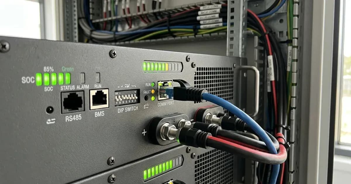
- Result: Confirm the communication cable is plugged into the CAN port (or A/CAN port) and NOT the Console port (RJ11/RS232) or the RS485 port — three physically different ports.
- Meaning: A cable in the wrong battery port commonly produces no communication at all — often with no error displayed (a community-reported trap).
- Verify RJ45 Pinout Configuration:
- Action: Check that your network cable matches the specific inverter-to-Pylontech pin map:
- CAN Bus Standard (Solis, Deye, Sungrow): Pin 4 = CAN-High (blue), Pin 5 = CAN-Low (blue-white) on both RJ45 plugs (with 500 kbps baud rate).
- Growatt SPF Series (L52 Protocol): Pins 4 and 5 carry CANH and CANL. When all 8 wires are connected on standard patch leads, the RS485 pair can interfere with the CAN signal. Strip or depin the cable so only pins 4 and 5 connect (the recommended cable leaves the first 3 pins null) if comms fail to establish.
- RS485 Port (Axpert King/VM III): Pin 7 = RS485A, Pin 8 = RS485B (recommended); alternate pinout: Pin 1 = RS485B, Pin 2 = RS485A; Pin 6 = GND.
- Inspect and Set Master Battery DIP Switches:
- Action: Inspect the DIP switch bank (Dip 1 to Dip 4) on the master battery.
- Result: For a standard single battery group, Dip 1 sets baud rate (0 = 115200, 1 = 9600), while Dip 2–4 set group addressing. Ensure the master switch is set to 0000 (or 1000 depending on inverter-specific master instructions).
- Meaning: DIP switch modifications take effect only after powering off the module and performing a complete restart.
- Confirm Inverter Protocol Programming:
- Growatt SPF 3500-5000 ES: Program 05 = "Li", Program 36 = "L52" (CAN) or "L04"/"L05" (RS485 on older firmware). Footnote c of the Pylontech compatibility list requires setting DoD to 80% or below on SPF/M series.
- Solis Hybrid (S5/S6): Advanced Settings (Password 0010) → Battery Select → select the Pylon option (shown as "PYLON" or "PYLON_LV" depending on firmware).
- Deye Hybrid (SUN-SG): Battery Type = "LITHIUM", Lithium Mode Protocol = "00" (CAN) or "12" (RS485).
- Inverex Nitrox / Axpert Manual Fallback: Installer walk-throughs (community-reported) show selecting the Pylon-specific "PYL"-type battery option on Nitrox; the verified sourced fallback is the official Voltronic-platform manual-settings SOP (Program 05 = "USE", Program 02 = N*25A, Program 26 = 53.2 V, Program 27 = 53.2 V, Program 29 = 47.5 V, Program 12 = 48V, Program 13 = 51V; all setpoints referenced to 25°C, where BMS throttles charging in high heat).
- Execute the Official Pylontech Cold Restart Sequence:
- Action: Power off AC grid and PV isolators → turn off inverter power switch → switch off red rocker switches on all battery modules (isolate power first and use insulated tools near terminals).
- Sequence: Wait 10 to 20 seconds → turn ON rocker switches on all batteries → press the red SW (Start) button on the MASTER module for 1 second (until all LEDs light).
- Result: The master battery's LEDs will illuminate, followed by slave modules cascading online. Finally, power on the inverter.
Inverter-Specific Pylontech Fault Resolution Table
Inverter platform | Displayed alarm / fault code | Root cause | Exact fix |
|---|---|---|---|
Solis S5/S6 Series | | Wrong CAN cable version or miswired RJ45 | Use Solis cable WIOSCAN30RJ1 (pins 4/5). Select "PYLON_LV" in Advanced Settings. |
Growatt SPF 3500-5000 ES | BMS communication loss (no verified numeric code — go by the symptom) | Program 36 mismatch or pin 1–3 RS485 cross-talk | Set Program 05 to "Li", Program 36 to "L52". Strip the cable so only pins 4/5 (CANH/CANL) connect. |
Deye SUN-(3-12)K-SG0x / SUN-SG01-04 | BMS communication error (no verified code number) | Protocol code incorrect or wrong port | Set Battery Type to "LITHIUM", Protocol Mode to "00" (or "12" for RS485). Ensure cable is in CAN port. |
Axpert VM III / King | | RS485 pinout mismatch or unsupported model | Verify RS485 pins 7/8 or 1/2. Non-VM III/King Axpert models require manual "USE" mode (Program 05 = USE, 53.2 V charge, referenced to 25°C). |
Victron MultiPlus / GX | Battery not detected / auto-shutdown | Using generic Pylon cable instead of Type-A | Replace cable with proprietary Victron Type-A VE.Can to CAN-bus BMS cable. |
Inter-Module Daisy Chaining and Master Selection Rules
When operating multi-battery Pylontech banks (e.g., 2× to 8× US3000C modules), correct inter-module cabling is critical:
- Designating the Master Module: The battery connected directly to the inverter via the CAN communication cable is the Master.
- Inter-Module Cabling and Addressing: Follow the link-cabling diagram in your model's own product manual for master-to-slave connections. Group addressing is set on DIP switches 2–4, and address changes take effect only after restarting the battery modules.
- Maximum String Capacity: Up to 16 Pylontech US3000C or US5000 modules can be connected in a single parallel string per the datasheet; older US3000 manual specifies 1 master + 7 slaves per group (8 per group) — check your model's manual.
- Cell Count Mixing Trap: Never mix 15-cell US-series modules (nominal 48V, charges ~53.2 V, referenced to 25°C) with 16-cell UF5000 units (~56 V charge, referenced to 25°C) in the same bank.
For broader compatibility troubleshooting, review our guide on lithium battery inverter compatibility errors. If the inverter shuts down without output, consult inverter shows error but no output and our master inverter error code glossary.
Safety: Working with Lithium-Ion (LiFePO4) Battery Racks
Observe these critical safety protocols when handling Pylontech rack systems:
- Dry Powder Extinguishers Only: The Pylontech US3000 manual safety section specifies only DRY POWDER extinguishers; liquid extinguishers are prohibited.
- Voltage Limits: Never apply charging voltages exceeding 54V to US-series modules. Exceeding 54V triggers charge over-voltage protection, and according to Wattuneed's Pylontech warranty claims guide, overvoltage >54V recorded in the BMS logs leads to refusal of a warranty claim.
- Thermal and Current Protection: Operating window spans 0-55C for charging and -10-55C for discharging (US5000). BMS protection triggers if temperature is outside -10 to 50C, current exceeds 100A, or voltage drops to <=44.5 V (US3000 manual). All normal charge setpoints are referenced to 25°C; the BMS throttles charging in high ambient heat per manufacturer operating windows (heat-derating numbers A per °C are unpublished; derating is qualitative).
- De-energize Before Servicing: Disconnect all AC grid breakers and DC battery isolators before modifying communication or power wiring. Always kill power first and use insulated tools around terminals because a spanner across a bank shorts hundreds of amps.
When to call a technician instead
Contact a certified solar technician or an authorized Pylontech distributor under the following conditions:
- The red ALM light remains solid (long-bright) after multiple cold restart attempts, indicating equipment failure or protection.
- Terminal voltage measures below 44.5 V (deep discharge protection threshold referenced to 25°C) and the battery refuses to take a charge, or reads >48V and still fails to discharge.
- Internal BMS diagnostic extraction is required: according to Wattuneed's Pylontech warranty claims guide, warranty claims (since Oct 2025) require internal
_history.txtand_event.txtBMS logs plus a completed claim form (decision 2-4 weeks, replacement 4-8 weeks). In Pakistan, AMS Security Vision claims authorized distributor/importer status.
For professional escalation standards, consult our guide on when to call a solar technician and our parent diagnostic guide on solar battery not charging.
Figures researched August 2026.
Still showing the fault? Book a technician
If the steps above did not clear it, tell us the inverter or battery and the exact code. We pass it to a technician who covers your city; visit charges are quoted before they come.
How this pays for the site: the technician or verifier pays SolarNevs a fixed introduction fee. Nobody pays to be recommended, and you are free to use our free guides instead.
Products mentioned
Frequently asked questions
What does a Pylontech communication fault or Batt_Comm_FAIL mean?
This alarm indicates the solar inverter cannot establish or maintain digital data exchange with the Pylontech BMS. As a result, the inverter cannot read state of charge, cell voltages, or allowable charge currents.
What is the RJ45 pinout for Pylontech CAN communication?
Pylontech CAN communication uses Pin 4 for CAN-High (blue) and Pin 5 for CAN-Low (blue-white) at 500 kbps. When connecting to inverters like the Growatt SPF series where standard patch cords connect all 8 wires, the cable must be stripped or depinned so only pins 4 and 5 (CANH and CANL) connect, removing the interfering RS485 pair (the recommended cable leaves the first 3 pins null).
Which protocol program code connects Pylontech to Growatt SPF inverters?
Set Program 05 to 'Li' and Program 36 to 'L52' for CAN communication. On older firmware, select 'L04' or 'L05' for RS485 communication. Additionally, per compatibility list footnote c, depth of discharge (DoD) must be set to 80% or below on SPF/M series to prevent low-SOC shutdown requiring manual recharge.
How do I configure DIP switches on Pylontech battery modules?
For a single battery bank group, set DIP switch 1 to 0 (115200 baud) and DIP switches 2–4 to 0 (address 0000 on the master battery). Any DIP switch changes take effect only after restarting the battery module.
What causes Error 61 on Voltronic and Axpert inverters?
Vendor and installer reports (community-level sources) link Error 61 on Voltronic-platform Axpert inverters to loss of BMS communication. Note that on Voltronic Axpert platforms, only VM III and King models support RS485 comms (requiring pins 7/8, or alternate pins 1/2), while other Axpert models require manual voltage settings (Program 05 = USE; bulk 53.2 V, float 53.2 V, cutoff 47.5 V; all setpoints referenced to 25°C where BMS throttles charging in high heat).
References
- Solis Service Pylontech Batt_Comm_FAIL Guide — accessed 23 August 2026
- Voltacon Solar Growatt to Pylontech US5000 Guide — accessed 23 August 2026
- Pylontech US3000 Product Manual PDF — accessed 23 August 2026
- Pylontech Inverter Compatibility List Ver 2.40 — accessed 23 August 2026
- Solis Communication Ports for Battery Connection — accessed 23 August 2026
- Solis Resetting Pylontech Batteries Guide — accessed 23 August 2026
- Victron Battery Compatibility Pylontech — accessed 23 August 2026
- Wattuneed Pylontech Diagnosis and Warranty Guide — accessed 23 August 2026
- MPP Solar Pylontech Inverter Setup SOP — accessed 23 August 2026
- Solar Deity Connecting Deye Hybrid Inverter to Pylon Battery Guide — accessed 23 August 2026
Related guides
More from inverter errors & fixes.