Pylontech Inverter Settings: Pairing US3000C and US5000
Updated 7 September 2026 · By SolarNevs Research Desk, Dealer surveys + verified sources · 10 sources · Method ↗
Key Takeaways
- Pylontech US-series (US2000C, US3000C, US5000) modules use a 15-cell LiFePO4 architecture requiring ~53.2 V full charge (15 cells in series equates to 3.55 V/cell; 52.4 V cap on Victron DVCC; all setpoints referenced to 25°C, where the BMS throttles charging in high ambient heat); charging voltage must never exceed 54V.
- On Growatt SPF 3500-5000 ES inverters, set Program 05 to Li and Program 36 to L52 over CAN on current firmware, or L04/L05 over RS485 on older units (sources record a firmware conflict); limit DoD to <=80% per compatibility list footnote c.
- On Deye hybrid inverters (SUN-(3-12)K-SG0x / SUN-SG01-04), select battery type LITHIUM, configure protocol 00 (CAN) or 12 (RS485), and set module capacity and charge amperage (US2000C: 50AH, 25A; US3000C: 74AH, 37A; UP5000: 100AH, 90A) with Activate Battery OFF.
- Voltronic Axpert platforms without VM III or King communication cards require manual voltage settings (Program 05 USE, Program 02 N*25A, Program 26 53.2 V, Program 27 53.2 V, Program 29 47.5 V, Program 12 48V, Program 13 51V; all setpoints referenced to 25°C, where BMS throttles charging in high ambient heat) per official Pylontech SOP.
Quick Answer: How to configure your inverter for Pylontech batteries
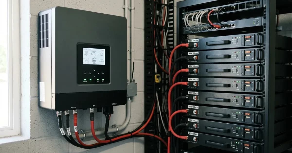
To correctly pair Pylontech US2000C, US3000C, or US5000 rack batteries with your solar inverter, connect a dedicated RJ45 communication lead between the battery Master CAN port (Pins 4 and 5) and the inverter BMS port. Configure your inverter for closed-loop lithium communication (such as protocol 00 on Deye, PYLON_LV on Solis, or L52 / L04/L05 on Growatt). Always isolate power before adjusting communication cables.
Once the digital communication link is established, the Pylontech BMS dynamically broadcasts real-time State of Charge (SOC), charge voltage targets (~53.2 V full charge on 15 cells, referenced to 25°C), and charge/discharge current limits. If your inverter platform does not support closed-loop RS485/CAN communication (Axpert platforms per footnote b), configure manual voltage mode: Program 05 to USE, Program 02 to N*25A, Program 26 and Program 27 to 53.2 V, Program 29 to 47.5 V, Program 12 to 48V, and Program 13 to 51V (all setpoints referenced to 25°C, noting that the BMS throttles charging in high ambient heat).
Master Pairing and Inverter Settings Table for Pylontech Batteries
The table below compiles verified closed-loop protocol parameters and manual voltage fallbacks (all voltage setpoints referenced to 25°C, noting BMS throttles charging in high ambient heat) across major inverter platforms sold in Pakistan:
Inverter Platform | Battery Type / Menu Setting | Protocol Code / Profile | Charge Voltage Target | Low DC Cutoff / Discharge Limit | Comms Physical Port / Cable |
|---|---|---|---|---|---|
Growatt SPF 3500-5000 ES | Program 05: Li | Program 36: L52 (CAN) or L04/L05 (RS485) | BMS-controlled once linked | Set DoD <=80% (compat list footnote c) | Straight RJ45, Pins 4/5 only (CANH/CANL), first 3 pins null |
Solis S5/S6-EH1P / RHI-48ES-5G | Advanced Settings (pass 0010) -> Battery Select | PYLON_LV (or PYLON per firmware) | BMS-controlled via CAN | Inverter Discharge Cutoff (No Battery if none) | CAN Pins 4/5; use Pylon-supplied cable for US5000 (WIOSCAN30RJ1) |
Deye SUN-(3-12)K-SG0x / SUN-SG01-04 | Battery Type: LITHIUM (Activate Battery OFF) | Lithium Mode: 00 (CAN) or 12 (RS485) | BMS-controlled (US2000C: 25A, US3000C: 37A, UP5000: 90A) | BMS-controlled / Inverter Cutoff | Battery A/CAN port -> Inverter CAN/RS485 port (Pins 4/5, DIP 0000) |
Victron MultiPlus / Quattro (via GX) | DVCC: ON | Automatic GX identification | 52.4 V (Victron 15-cell limit) | Controlled by GX DVCC logic | Mandatory Type-A VE.Can to CAN-bus BMS cable |
Axpert / Inverex (Manual Mode) | Program 05: USE (User-Defined) | Manual fallback per Pylontech SOP (Program 02 = N*25A) | Program 26 / 27: 53.2 V | Program 29: 47.5 V (Prog 12: 48V / Prog 13: 51V) | Manual voltage mode; no digital comms required (footnote b) |
Figures as of August 2026. All voltage setpoints are referenced to 25°C (operating window 0–55°C charge, where the BMS throttles charging in high ambient heat).
Step-by-Step Configuration Workflow
1. The 15-cell Architecture Rule
Pylontech US-series batteries (US2000C, US3000C, US5000) are constructed using 15 series-connected LiFePO4 cells rather than standard 16-cell configurations.
- Voltage Architecture: US-series modules feature a 48V nominal rating and charge at ~53.2 V (referenced to 25°C, where BMS throttles charging in ambient heat); 15 cells in series equates to 3.55 V/cell.
- Victron Exception: Victron Energy caps charge voltage at 52.4 V under DVCC control for the 15-cell US series (referenced to 25°C) to eliminate cell over-voltage tripping.
- Do Not Mix Cell Counts: Never mix 15-cell US-series modules (charge ~53.2 V, referenced to 25°C) with 16-cell modules (such as the UF5000, which charges at ~56 V, referenced to 25°C) in the same battery bank. The manufacturer compatibility documentation notes that pairing voltages differ and modules cannot be mixed in one bank, preventing severe circulating currents and BMS lockouts.
2. Growatt SPF Inverter Protocol Selection and Conflict Resolution
On Growatt SPF 3500-5000 ES inverters:
- Configure Program 05 to Li.
- The Protocol Conflict: Voltacon documentation records Program 36 code L52 over CAN bus on current firmware, while Growatt commissioning documentation (via amosplanet) lists codes L04 / L05 over RS485 as first priority on older firmware. Installers recommend testing L52 over CAN first, falling back to L04/L05 over RS485 if CAN communication is not established.
- Comms Cable Pinout: Build a straight RJ45 cable connected to pins 4 and 5 only (pin 4 CANH, pin 5 CANL) with the first 3 pins null, preventing RS485 pair interference.
- Depth of Discharge Limit: Pylontech compatibility list footnote c mandates setting maximum DoD to <=80% on Growatt SPF/M series to prevent low-SOC shutdown states that require manual DC black-start charging.
3. Deye Hybrid Inverter Configuration
On Deye hybrid inverters (SUN-(3-12)K-SG0x and SUN-SG01-04):
- Navigate to Battery Setup -> select LITHIUM.
- Set Lithium Mode protocol to 00 for CAN communication (or 12 for RS485 Modbus).
- Enter module parameters: US2000C ("50AH, 25A, 25A"), US3000C ("74AH, 37A, 37A"), or UP5000 ("100AH, 90A, 90A").
- Ensure Activate Battery remains OFF during normal closed-loop operation.
- Set single battery DIP switch to 0000 (or 1000 per Master Setting 1).
4. Voltronic Axpert and Inverex Nitrox Integration
According to Pylontech compatibility list footnote b, within the Voltronic Axpert family, only VM III and King models support closed-loop RS485 communication. For standard Axpert models and Inverex platforms where closed-loop communication is unavailable, follow the official Pylontech/MPP Solar setup SOP (with all setpoints referenced to 25°C, where BMS throttles charging in high heat):
- Program 05: USE (User-Defined)
- Program 02 (Max Charge Current): N*25A (where N is the number of parallel modules)
- Program 26 (Bulk/CV): 53.2 V (referenced to 25°C baseline, where BMS throttles charging in high ambient heat)
- Program 27 (Float): 53.2 V (referenced to 25°C baseline, where BMS throttles charging in high ambient heat)
- Program 29 (Low DC Cutoff): 47.5 V (referenced to 25°C baseline, where BMS throttles charging in high ambient heat)
- Program 12 (Back to Grid): 48V (referenced to 25°C baseline)
- Program 13 (Back to Discharge): 51V (referenced to 25°C baseline)
(Note: While some installer videos show a community-reported "PYL" option on Inverex Nitrox units, the manual-settings profile above represents the verified manufacturer-approved fallback per compatibility list footnote b).
5. Multi-Module String Sizing and DIP Switch Addressing
- String Capacity Limits: Current US3000C and US5000 datasheets allow paralleling up to 16 modules per string without an external hub. Note that older US3000 product manuals specified a limit of 1 master plus 7 slaves per group (8/group); always follow your specific module revision manual.
- DIP Switch Rules: On single-group installations, leave the Master DIP switch set to 0000 (or 1000). DIP 1 toggles baud rate (0 = 115200 bps, 1 = 9600 bps), while DIP 2-4 set group addresses. Battery power must be restarted after adjusting DIP switches for changes to take effect.
- Commissioning Sequence: Turn off inverter -> turn off battery rocker switches -> wait 10-20s -> turn on rocker switches -> press the red SW button on the Master module for ~1s until all LED indicators illuminate.
For communication cable pinouts and RJ45 crimping rules, consult our guide on Pylontech communication fault fixes and decode front-panel indicators in Pylontech SOC and alarm light meanings. Understand protocol mismatches in our guide on lithium battery inverter compatibility errors and learn internal BMS protection architectures in BMS functions and battery protection.
Safety: LiFePO4 Handling and Protection Limits
Observe these mandatory safety protocols when installing and configuring Pylontech modules:
- 54V Voltage Ceiling: Never apply charging voltages exceeding 54V (referenced to 25°C). Charging above 54V triggers instant BMS over-voltage protection and leads to warranty refusal per the Wattuneed claims guide. Never equalize a lithium battery.
- Fire Extinguisher Standard: Pylontech product manuals mandate using DRY POWDER extinguishers only. Liquid fire extinguishers are strictly prohibited around energized lithium racks.
- Thermal Operating Bounds: Operating temperature windows are 0-55C for charging and -10-55C for discharging (cycle life specified @25C on US5000). The BMS throttles charging in high ambient heat (heat-derating numbers A per °C are unpublished; derating is qualitative).
- Storage Recommendation: Manual advises SOC no less than 90% before long storage.
- Hardware Protection Limits: US3000 manual protection thresholds (referenced to 25°C operating baseline) include over-temp >50C / under-temp <-10C, over-current >100A, charge over-voltage >54V, and discharge under-voltage protection at 44.5 V.
- Electrical Handling Precautions: Isolate PV array and grid power before recabling communication lines. Kill power first and use insulated tools whenever servicing battery power terminals (a metal spanner across energized terminals can short hundreds of amperes). Torque battery power terminals strictly per manual specifications and route communication cables away from high-current power cables to prevent electromagnetic interference.
When to call a technician instead
Contact an authorized Pylontech distributor or certified solar installer under the following conditions:
- The Master module red ALM LED illuminates solid red and refuses to reset after a full power cycle (indicating hardware failure or protection lockout where charge/discharge is refused).
- The battery won't discharge and voltage is <44.5 V (deep discharge protection); if recharged to >48V (referenced to 25°C) and the pack remains non-operational, contact distributor support.
- Assistance is required to retrieve BMS diagnostic event logs (_history.txt / _event.txt) using service software for warranty submission (Wattuneed claims guide records 2-4 weeks for decisions and 4-8 weeks for replacement; overvoltage >54V in logs results in claim refusal).
- Verification of authentic imported units with holographic seals and portal-verifiable serial numbers is required (AMS Security Vision claims authorized distributor/importer status in Pakistan with offices in Lahore, Karachi, and Rawalpindi).
For professional maintenance standards, consult our guide on when to call a solar technician.
Still showing the fault? Book a technician
If the steps above did not clear it, tell us the inverter or battery and the exact code. We pass it to a technician who covers your city; visit charges are quoted before they come.
How this pays for the site: the technician or verifier pays SolarNevs a fixed introduction fee. Nobody pays to be recommended, and you are free to use our free guides instead.
Frequently asked questions
What is the correct charging voltage for Pylontech US-series batteries?
Pylontech US-series batteries (US2000C, US3000C, US5000) use a 15-cell LiFePO4 architecture with a nominal voltage of 48V and a full charge voltage of ~53.2 V, which equates to 3.55 V/cell (capped at 52.4 V on Victron DVCC; all ratings referenced to 25°C, where the BMS throttles charging in high ambient heat per manufacturer operating windows as derating numbers are unpublished and qualitative). Charging voltage must never exceed 54V to prevent BMS over-voltage protection lockouts and warranty refusal.
How do I configure a Growatt SPF 3500-5000 ES for Pylontech batteries?
Set Program 05 to 'Li'. For Program 36, sources record a firmware-dependent conflict: set 'L52' for CAN communication on current firmware, or 'L04/L05' over RS485 on older units (try L52 over CAN first). Limit Depth of Discharge (DoD) to <=80% per Pylontech compatibility list footnote c to avoid low-SOC shutdowns needing manual recharge. For CAN (L52), use a straight RJ45 cable wired on pins 4 and 5 only (pin 4 CANH, pin 5 CANL, first 3 pins null); the L04/L05 RS485 fallback uses the battery RS485 port instead (pins 7 RS485A / 8 RS485B per the US3000 manual).
What protocol settings should I use for a Deye hybrid inverter with Pylontech?
In the Deye Battery Setup menu, select 'LITHIUM' and configure Lithium Mode protocol to '00' for CAN bus communication (or '12' for RS485). Set battery capacity and charge current limits matching your module (e.g. 50AH, 25A for US2000C; 74AH, 37A for US3000C; or 100AH, 90A for UP5000), and keep 'Activate Battery' OFF.
Can I mix Pylontech US-series modules with UF5000 modules in the same bank?
No. The US series uses a 15-cell LiFePO4 architecture (charges ~53.2 V, referenced to 25°C), whereas the UF5000 uses a 16-cell architecture (~56 V charge, referenced to 25°C). Pairing voltages differ and modules cannot be mixed in one bank; paralleling them causes severe circulating currents and BMS lockouts.
What settings should I use if closed-loop BMS communication fails on an Axpert inverter?
If closed-loop communication is unavailable (Axpert non-VM-III/King platforms per compatibility list footnote b), use official Pylontech manual settings: Program 05 to 'USE', Program 02 to N*25A, Program 26 (Bulk) to 53.2 V, Program 27 (Float) to 53.2 V, Program 29 (Low Cutoff) to 47.5 V, Program 12 to 48V, and Program 13 to 51V (all setpoints referenced to 25°C; BMS throttles charging in high ambient heat).
References
- Pylontech Inverter Compatibility List Ver 2.40 — accessed 23 August 2026
- Solis Communication Ports for Battery Connection — accessed 23 August 2026
- MPP Solar Official Pylontech Inverter Setup SOP — accessed 23 August 2026
- Victron Energy Pylontech Battery Compatibility Manual — accessed 23 August 2026
- Voltacon Knowledge Base Growatt to US5000 Guide — accessed 23 August 2026
- Growatt Lithium Battery Commissioning Guide via Amosplanet — accessed 23 August 2026
- Wattuneed Pylontech Warranty and Diagnosis Guide — accessed 23 August 2026
- Pylontech US3000 Product Manual — accessed 23 August 2026
- Solis Resetting Pylontech Batteries Guide — accessed 23 August 2026
- Solar Deity Deye Hybrid Inverter to Pylon Battery Guide — accessed 23 August 2026
Related guides
More from inverter errors & fixes.