Victron VE.Bus Communication Errors: Fix Guide and Cause Table
Updated 6 September 2026 · By SolarNevs Research Desk, Dealer surveys + verified sources · 1 source · Method ↗
Key Takeaways
- Electromagnetic interference (EMI) from power cables is the most common cause of VE.Bus communication errors.
- The first diagnostic step is to examine the network quality counters via VRM to quantify error rates.
- Always disconnect power from all sources (PV, battery, AC) before working with cabling to prevent electric shock or equipment damage.
- Stop DIY troubleshooting and consult a qualified technician if errors persist after following all cable management and ferrite core recommendations.
How do I fix Victron VE.Bus network interference?
Victron VE.Bus network interference is primarily caused by electromagnetic interference (EMI) from nearby power cables affecting the communication lines. The most common cause is improper cable routing and lack of separation between power and data cables. The first step to fixing this is to check the VE.Bus network quality counters to understand the extent of the problem.
Diagnosis
Follow these steps to diagnose VE.Bus network interference:
- Check Network Quality Counters:
- Access these counters via VRM by adding
/diagnosticsto the VRM URL for your site. - These counters track the number of frame retransmissions required after a VE.Bus device receives an invalid frame.
- Reset the VE.Bus system on the GX device in the Multi Advanced menu.
- After commissioning and a system reset, a count should be 0. If it is a new system and the count is more than 10, there is a problem.
- If there is variation in the counter levels between units, focus your attention on those with higher numbers.
- Access these counters via VRM by adding
- Inspect Cable Routing and Separation:
- Visually inspect all VE.Bus communication cables.
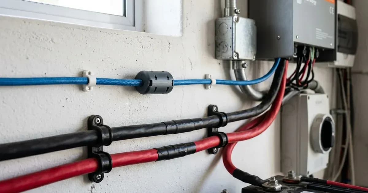
- Check for instances where communication cables are bundled with power cables (DC solar, AC, or DC battery cables). Bundling power and comms cables together should always be avoided.
- Note the distance between communication cables and power cables. Interference intensity is 100% at 1 cm, 25% at 2 cm, and approximately 11.11% at 3 cm. At 10 cm, it is only 1%, and at 20 cm, it can usually be assumed safe.
- DC solar cables are most likely to cause interference, followed by AC cables, which are more likely to cause interference than DC battery cables. Other data communications cables rarely cause interference.
- Verify Cable Type and Length:
- Ensure all VE.Bus cables are manufactured cables. Avoid using cables crimped onsite.
- Check if cable lengths are minimized. Excessively long or coiled cables can increase susceptibility to interference. Use a shorter manufactured cable if possible.
- Confirm Network Topology:
- The VE.Bus network is a bus topology. It is not a ring or any other configuration.
- Ensure the arrangement is a single RJ45 cable link from the GX device to the first VE.Bus inverter/charger, and then daisy chain to subsequent VE.Bus inverter/chargers if they exist.
- There is no termination required at either end, nor should any be used. The end-ports of the VE.Bus should be left open, or blanked out with no connection made. Do not loop the cable around to those end points.
Cause/fix table
Symptom detail | Likely cause | Fix |
|---|---|---|
High network quality counters (above 10 after reset) | Electromagnetic interference (EMI) from nearby power cables. | Re-route communication cables to maintain separation; maintaining separation is important, and bundling power and comms cables together should always be avoided. If errors persist, they likely need to be re-routed. |
Intermittent VE.Bus communication, system instability | Insufficient separation between communication and power cables. | Increase separation distance. Aim for 10 cm for 1% interference, or 20 cm for usually safe operation. |
"Error 3 - Not all, or more than, the expected devices were found in the system" in large configurations | Incorrect cable type or improper network topology. | Always use manufactured cables rather than crimping them onsite. Ensure a bus topology: GX to first inverter, then daisy chain to others. Do not use termination. |
Persistent errors despite cable routing adjustments | Residual electromagnetic noise. | Install Ferrite core noise suppressing cable clips. Some Ferrite core clips are supplied with GX devices and should be attached to the GX cables. If errors persist, install ferrites on each communications cable in the system at each point of connection, including between each inverter, between the master inverter and the GX, and the battery comms cables. |
Slow or unreliable communication in small setups | Minor delays and retransmissions. | In smaller setups with a single unit, delays and retransmissions from a Multi to a GX device may not even have noticeable effects. However, improving cable management can prevent future issues. |
Communication System Overview
The Victron VE.Bus network operates as a bus topology, meaning devices are connected in a linear sequence, typically daisy-chained. This design is sensitive to electromagnetic interference (EMI), which can corrupt data signals and lead to communication errors.
To ensure reliable communication, always use manufactured cables rather than crimping them onsite. These cables are designed for signal integrity. Minimize cable lengths where possible and avoid bundling or coiling excess cable, as this can increase susceptibility to noise.
Electromagnetic interference is a significant factor. Power cables, especially DC solar cables and AC cables, are the most likely to cause interference. Maintaining physical separation between communication cables and power cables is critical. For example, at 10 cm distance, interference is reduced to only 1%, and at 20 cm, it can usually be assumed safe.
For persistent issues, ferrite core noise suppressing cable clips can be effective. Some are supplied with GX devices and should be attached to the GX cables to reduce in-line noise and interference. If VE.Bus network errors persist, install ferrites on each communications cable in the system at each point of connection, including between each inverter, between the master inverter and the GX, and the battery comms cables.
The VE.Bus system includes network quality counters that track the number of frame retransmissions. These counters can be accessed via VRM by adding /diagnostics to the VRM URL for a site. After a VE.Bus system reset, a count should be 0. If it’s a new system and it’s more than 10, there is a problem. Monitoring these counters helps identify units experiencing higher error rates, allowing you to focus troubleshooting efforts.
Safety
Before performing any work on your Victron system, especially involving cabling, prioritize safety. Disconnect all power sources: turn off PV array breakers, disconnect battery banks, and switch off AC input breakers. Verify that no voltage is present using a multimeter. Use insulated tools to prevent accidental short circuits, as a spanner across a battery bank can short hundreds of amps, causing severe burns or equipment damage. Always be aware that high currents are present in power cables, and improper handling can lead to electric shock or fire.
When to call a technician instead
If VE.Bus network errors persist after you have followed all cable management, separation, and ferrite core recommendations, it is time to consult a qualified Victron Energy technician. Complex communication issues can sometimes indicate internal hardware faults or require specialized diagnostic tools beyond typical DIY capabilities. Attempting further repairs without proper training or equipment could void your warranty or cause additional damage to your system.
Frequently asked questions
What causes VE.Bus network interference?
VE.Bus network interference is often caused by electromagnetic interference (EMI) from nearby power cables, especially DC solar and AC cables, affecting the communication lines. Other data communication cables rarely cause interference.
How far should VE.Bus cables be from power cables?
To minimize interference, VE.Bus communication cables should be separated from power cables. At 10 cm distance, interference is reduced to only 1%, and at 20 cm, it can usually be assumed safe.
How can I check for VE.Bus network errors?
You can check network quality counters via VRM by adding `/diagnostics` to the VRM URL for your site. These counters track frame retransmissions. After a VE.Bus system reset, a count above 10 indicates a problem in a new system.
Should I use manufactured VE.Bus cables?
Yes, always use manufactured cables rather than crimping them onsite. Minimize cable lengths where possible and avoid bundling or coiling excess cable.
Can ferrite core clips help with VE.Bus interference?
Yes, the use of Ferrite core noise suppressing cable clips can help filter out noise. If VE.Bus network errors persist, install ferrites on each communications cable in the system at each point of connection.
References
- Victron Energy VE.Bus Network Interference Guide — accessed 23 August 2026
Related guides
More from what to buy — and how not to get cheated.