Victron VE.Bus Network Interference Troubleshooting
Updated 16 September 2026 · By SolarNevs Research Desk, Dealer surveys + verified sources · 1 source · Method ↗
Key Takeaways
- Most VE.Bus issues stem from communication cabling or electromagnetic interference (EMI).
- Start by inspecting all physical cable connections and reviewing cable routing.
- Always use manufactured VE.Bus cables; never use custom-crimped ones.
- If basic checks and cable management do not resolve the issue, consider adding ferrite core cable clips.
Why is my Victron VE.Bus system showing errors or behaving erratically?
Victron VE.Bus systems often experience errors or erratic behavior due to issues with the communication cabling or electromagnetic interference (EMI). These problems can manifest as spurious error codes, high network error counts, or system instability. The first step is to physically inspect all VE.Bus connections and cable routing within your system.
Diagnosis
Follow these steps to diagnose potential VE.Bus network interference or cabling issues.
- Check physical connections. Ensure all VE.Bus cables are securely plugged into the correct ports on your GX device and Inverter/chargers. Loose connections are a common cause of communication problems.
- Inspect cable type and condition. The VE.Bus network relies on standard UTP (Unshielded Twisted Pair) cables. Victron states that you should "always use manufactured cables rather than crimping them onsite for VE.Bus connections." Verify that your cables are not damaged, kinked, or excessively coiled.
- Review cable routing. "Maintain separation between power cables and communication cables; avoid bundling them together." DC solar cables are identified as "most likely to cause interference, followed by AC cables." Ensure your VE.Bus cables are routed away from these power conductors.
- Check cable length. "Minimize the length of communication cables and avoid bundling or coiling excess." Longer cables or coiled excess can act as antennas, increasing susceptibility to EMI.
- Monitor network quality counters. If your system is connected to the Victron Remote Management (VRM) portal, you can access detailed network diagnostics. Add
/diagnosticsto the end of your site's VRM URL (e.g.,https://vrm.victronenergy.com/site_id/diagnostics). Look for "network quality counters" to identify invalid frame reception or checksum failures, which indicate communication problems. - Look for specific error codes. An "Error 3 - Not all, or more than, the expected devices were found in the system" specifically points to an issue with the number of devices detected on the VE.Bus network, often due to cabling.
Cause/fix table
Symptom detail | Likely cause | Fix |
|---|---|---|
Spurious VE.Bus error codes | VE.Bus cable issues, physical and EM interference, load types/sizes, AC input connection/disconnection, temperature, physical disturbance, age, corrosion | Inspect all VE.Bus cables for damage and secure connections. Re-route cables to separate them from power cables. Consider adding ferrite core cable clips. |
High VE.Bus network error count | Invalid frame reception, checksum failure, physical and EM interference | Improve cable shielding by using manufactured cables. Reduce EMI sources by re-routing. Check cable integrity and replace if damaged. |
Delays and retransmissions in small systems | Underlying VE.Bus network errors | Address cable quality and electromagnetic interference as primary causes. Ensure proper cable routing and use of manufactured cables. |
System shutdown in parallel system | Missing Multi unit (application level) | Verify all Multi units are connected and communicating on the VE.Bus network. Check each unit's VE.Bus connection. |
Error 3: "Not all, or more than, the expected devices were found in the system." | Incorrect number of devices detected on VE.Bus network, often due to cabling issues | Check all VE.Bus network connections and cabling, especially in large systems, to ensure every expected device is properly connected. |
Communication Network Checks
The Victron VE.Bus network is a robust communication system designed to allow Victron Inverter/chargers and GX devices to communicate. It uses a bus topology, meaning devices are connected in a chain.
VE.Bus Network Topology and Cabling
The VE.Bus network uses standard UTP (Unshielded Twisted Pair) cables. "Always use manufactured cables rather than crimping them onsite for VE.Bus connections" to ensure proper termination and shielding. The network should be daisy-chained: "daisy chain from the GX device to the first inverter/charger and then to subsequent ones." Importantly, "no termination is required at either end of the VE.Bus network; end-ports should be left open or blanked out."
Cable Routing and EMI Mitigation
Electromagnetic interference (EMI) is a significant cause of VE.Bus issues. To minimize EMI:
- Separation: "Maintain separation between power cables and communication cables; avoid bundling them together." "DC solar cables are most likely to cause interference, followed by AC cables."
- Length: "Minimize the length of communication cables and avoid bundling or coiling excess."
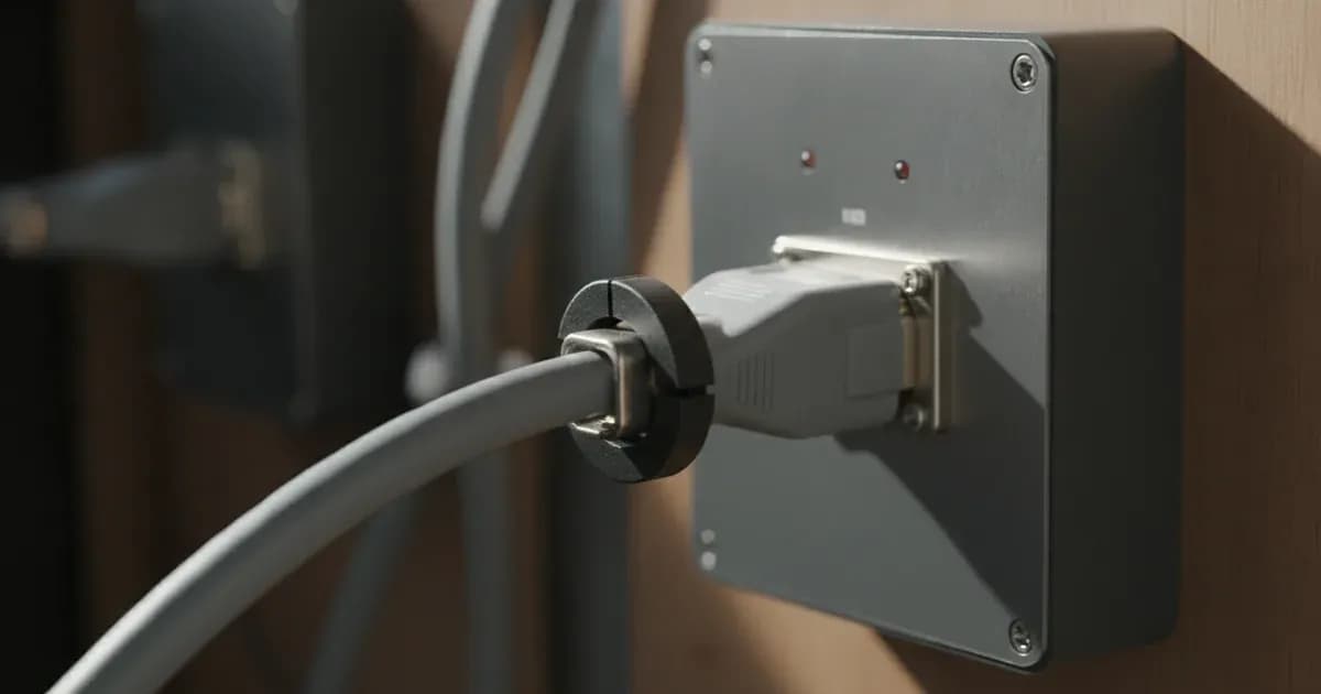
- Ferrite Cores: "Install ferrite core cable clips on GX cables and, if errors persist, on each communications cable in the system at each point of connection." These clips help suppress high-frequency noise on the communication lines.
Monitoring with VRM Diagnostics
For advanced troubleshooting, the VRM portal offers network quality counters. By adding /diagnostics to your site's VRM URL, you can view metrics like "invalid frame reception" and "checksum failure." A high count for these indicates communication problems. While the manual does not specify exact thresholds, a count "more than 10 for a new system" is generally considered problematic by installers.
VE.Bus System Reset
Victron documentation mentions a "VE.Bus system reset" as a setting, but does not detail the procedure or its location (e.g., in the Multi Advanced menu on the GX device). If other troubleshooting steps fail, consulting the GX device manual for a system reset option might be necessary, but proceed with caution as this can disrupt system operation.
Safety
When working with any electrical system, always prioritize safety. Before inspecting or manipulating cables, ensure all AC and DC power sources to the Victron equipment are disconnected. A spanner across a battery bank can short hundreds of amps, causing severe burns and equipment damage. Always use insulated tools when working near battery terminals.
When to call a technician instead
While many VE.Bus issues can be resolved with careful inspection and cable management, some problems require professional intervention. If you have followed all troubleshooting steps, ensured proper cabling, and applied ferrite cores without resolving the errors, it is time to contact a qualified Victron Energy installer. They have specialized tools and expertise to diagnose internal hardware faults or complex system configurations that may be causing the interference. Attempting repairs beyond basic cable management can void your warranty or cause further damage.
Frequently asked questions
What causes VE.Bus network errors?
VE.Bus errors are often caused by physical cable issues, electromagnetic interference (EMI), or improper network topology. These can lead to spurious error codes or high network error counts.
How can I check for VE.Bus network quality?
You can access network quality counters via the Victron Remote Management (VRM) portal. Add `/diagnostics` to your site's VRM URL to view these counters and assess network health.
Should I use custom-made VE.Bus cables?
No, Victron recommends always using manufactured cables for VE.Bus connections. This ensures proper shielding and reliable communication, which is crucial for system stability.
How should I route VE.Bus cables to avoid interference?
Maintain separation between power and communication cables, minimize cable length, and avoid bundling or coiling excess cable. DC solar cables are the most likely source of interference.
What is Error 3 on a Victron VE.Bus system?
Error 3, 'Not all, or more than, the expected devices were found in the system,' indicates that the system detected an unexpected number of devices on the VE.Bus network, suggesting a cabling or connection issue.
References
- Victron Energy VE.Bus Network Interference Guide — accessed 23 August 2026
Related guides
More from what to buy — and how not to get cheated.