What Causes Victron VE.Bus Communication Errors? Network Interference Explained
Updated 6 September 2026 · By SolarNevs Research Desk, Dealer surveys + verified sources · 1 source · Method ↗
Key Takeaways
- The most likely cause of VE.Bus communication errors is electromagnetic interference from power cables.
- The first check involves inspecting physical cable connections, routing, and separation from power lines.
- Always disconnect all power sources (AC, DC, PV) before working on any wiring to prevent electric shock or damage.
- If errors persist after following all troubleshooting steps, especially if they involve internal components, consult a qualified Victron technician.
What causes Victron VE.Bus communication errors?
Victron VE.Bus communication errors are commonly caused by electromagnetic interference (EMI) from power cables, poor cable quality, or physical disturbances to the network wiring. These issues can lead to spurious error codes, system instability, or high network error counts.
Diagnosis
Diagnosing VE.Bus communication issues involves systematically checking for common interference sources and verifying network integrity.
- Check for Error Codes:
- Observable check: Your Victron system displays an error code, such as "Error 3".
- What it means: "Error 3 - Not all, or more than, the expected devices were found in the system.” This indicates a discrepancy in the number of devices detected on the VE.Bus network compared to the system's configuration. This can be due to a disconnected device, a faulty cable, or severe interference preventing proper device enumeration.
- Action: Proceed to check physical connections and cable quality.
- Monitor Network Quality Counters:
- Observable check: Access your VRM portal and add
/diagnosticsto the URL for your site (e.g.,https://vrm.victronenergy.com/site-id/diagnostics). Look for "network quality counters" in the VE.Bus system diagnostics. - What it means: High network error counts, specifically invalid frames requiring retransmissions, indicate that the VE.Bus signals are being corrupted. This is a direct sign of interference or poor cable quality.
- Action: If counters are high, investigate cable routing and consider adding ferrite cores. You can reset these counters via the GX device Multi Advanced menu to track new errors after making changes.
- Observable check: Access your VRM portal and add
- Inspect Physical Cable Routing:
- Observable check: Visually trace all VE.Bus communication cables. Note their proximity to power cables (DC solar, AC, DC battery cables).
- What it means: "Avoid bundling power and communication cables together to prevent interference." DC solar cables are most likely to cause interference, followed by AC cables. DC battery cables are less likely. "Maintain physical separation between power and communication cables; 10 cm reduces interference to 1% of 1 cm intensity."
- Action: Reroute VE.Bus cables to maximize separation from all power cables. Aim for at least 10 cm of physical distance.
- Verify Cable Quality and Type:
- Observable check: Examine the VE.Bus cables for any signs of damage, kinks, or poor crimping. Identify if they are factory-manufactured or custom-made onsite.
- What it means: "Use manufactured cables; onsite crimping increases noise." Poor quality or damaged cables can introduce noise and signal degradation, leading to communication errors.
- Action: Replace any damaged cables. If custom-made cables are suspected, replace them with Victron-manufactured VE.Bus cables. "Minimize cable lengths, especially when parallel to power cables, to reduce signal weakening and noise."
Cause/fix table section
Symptom detail | Likely cause | Fix |
|---|---|---|
Spurious VE.Bus error codes, exacerbated by load types, load sizes, AC input connection/disconnection, temperature, physical disturbance, age, corrosion. | VE.Bus network interference from physical and electromagnetic sources. | Improve physical separation between communication and power cables (aim for 10 cm or more). Install ferrite core cable clips on all communication cables at each connection point. |
High network error count in VE.Bus system diagnostics. | Invalid frames requiring retransmissions due to interference or poor cable quality. | Replace any onsite crimped cables with manufactured cables. Ensure proper cable routing with maximum separation from power cables. Add ferrite core cable clips to GX cables and all communication cables if errors persist. |
Error 3 - Not all, or more than, the expected devices were found in the system. | Application-level error due to missing device, but protocol-level frames are still sent correctly (no checksum failure). | Verify all physical VE.Bus connections are secure. Check cable lengths and ensure they are not excessively long, especially near power cables. Ensure all expected devices are powered on and functioning. |
VE.Bus Network Specifics
The VE.Bus is a proprietary communication network designed for Victron Energy devices. It uses a bus topology, meaning devices are daisy-chained together.
- Network Topology: The VE.Bus system utilizes a bus topology. This means you connect the GX device to the first inverter/charger, and then daisy-chain to subsequent units in the system.
- Termination: Unlike some other bus systems, "VE.Bus end-ports" should be "Left open or blanked out; no termination required." Do not install termination resistors on the VE.Bus network.
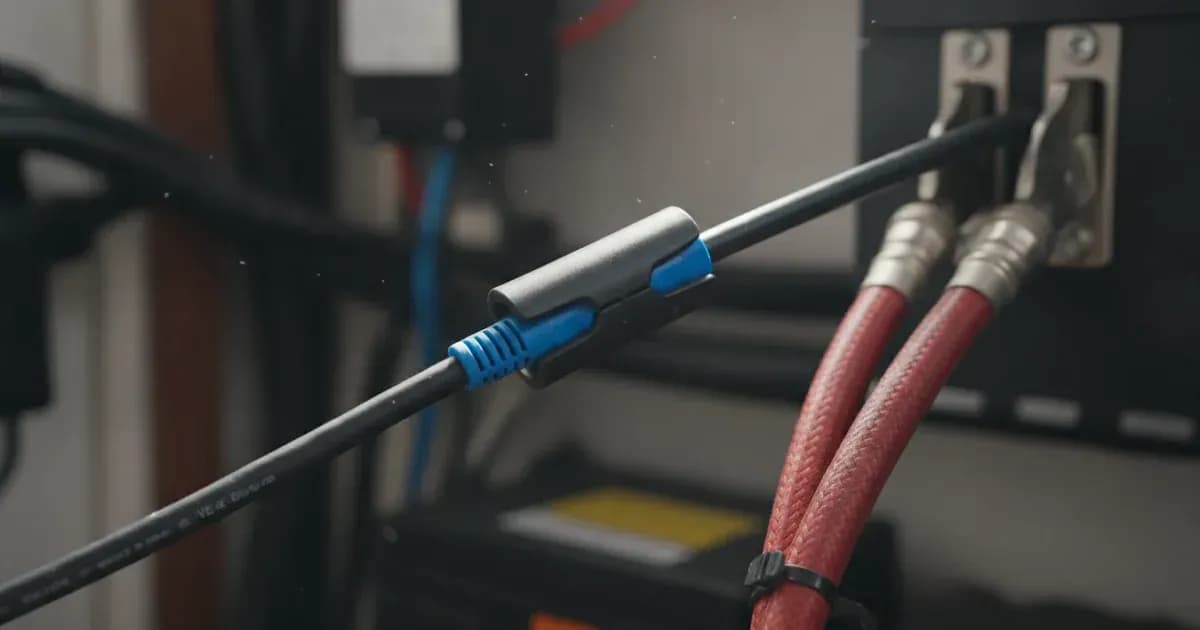
- Interference Mitigation: "Ferrite core cable clips" are recommended, especially on GX cables (often supplied) and on all communication cables if VE.Bus errors persist. These should be installed "at each point of connection" to help filter out electromagnetic noise.
Safety: Working with Electrical Systems
Working on any electrical system carries inherent risks. Always prioritize safety.
- Disconnect Power: Before inspecting or handling any wiring, ensure all power sources are disconnected. This includes AC input, DC battery power, and any solar PV input. Verify with a multimeter that no voltage is present.
- Insulated Tools: Use only insulated tools when working on electrical connections to prevent accidental short circuits.
- Cable Management: Proper cable management is not just for aesthetics; it is a critical safety measure. "Avoid bundling power and communication cables together to prevent interference." Incorrect routing can lead to system instability and potential hazards.
When to call a technician instead
While many VE.Bus communication issues can be resolved with careful troubleshooting, there are limits to DIY repairs. If you have followed all the steps above and still experience persistent errors, or if the issue involves internal components of a Victron device, it is time to call a qualified technician. Attempting repairs beyond basic cable management and external checks can void your warranty or lead to further damage. A technician has specialized tools and knowledge to diagnose complex issues and ensure your system operates safely and efficiently.
Frequently asked questions
What causes Victron VE.Bus communication errors?
Victron VE.Bus communication errors are commonly caused by electromagnetic interference from power cables, poor cable quality, or physical disturbances to the network wiring. These issues can lead to spurious error codes or high network error counts.
How can I check for VE.Bus network interference?
You can check for VE.Bus network interference by observing error codes like 'Error 3' on your Victron system. Additionally, you can monitor network quality counters by adding `/diagnostics` to your VRM URL for a site, which will show invalid frames requiring retransmissions.
What is Error 3 in a Victron VE.Bus system?
Error 3 in a Victron VE.Bus system indicates that the system found an unexpected number of devices, either too few or too many, compared to what was anticipated. This often points to physical connection issues or cable problems.
How do I reduce interference on VE.Bus cables?
To reduce interference, maintain physical separation between VE.Bus communication cables and power cables, ideally 10 cm or more. Use manufactured cables instead of onsite crimped ones, minimize cable lengths, and install ferrite core cable clips at connection points.
Does the Victron VE.Bus network require termination?
No, the Victron VE.Bus network does not require termination. The VE.Bus end-ports should be left open or blanked out, as specified in the system's design.
References
- Victron Energy VE.Bus Network Interference Whitepaper — accessed 23 August 2026
Related guides
More from what to buy — and how not to get cheated.