FoxESS H1 And H3 Hybrid Inverter BMS Communication Wiring Guide
Updated 15 September 2026 · By SolarNevs Research Desk, Dealer surveys + verified sources · 4 sources · Method ↗
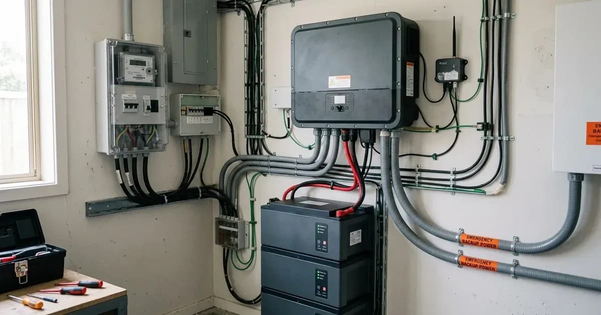
Key Takeaways
- FoxESS H1 and H3 BMS communication requires shielded twisted pair cabling.
- Smart meters for these inverters must be installed at the main grid connection point.
- EPS emergency power supply commissioning needs verification using official mobile tools.
- All high-voltage DC, AC grid, and switchgear modifications must be carried out by certified, licensed personnel.
How do I wire BMS communication, smart meters, and EPS for FoxESS H1 and H3 inverters?
Wiring FoxESS H1 single-phase and H3 three-phase hybrid inverters for BMS communication, smart meters, and EPS backup involves specific cable types and connection points. All high-voltage DC, AC grid interconnection, and switchgear modifications must be performed by certified, licensed personnel. This ensures safety and compliance with regulations.
Understanding the Communication and Power Mechanisms
FoxESS H1 and H3 hybrid inverters rely on various communication links and power connections to function correctly within a solar energy system. The Battery Management System (BMS) communication, often via CAN bus, allows the inverter to precisely control battery charging and discharging based on the battery's state of charge and health. RS485 communication is typically used for smart meters, enabling the inverter to monitor grid import and export, which is crucial for energy management and compliance. The Emergency Power Supply (EPS) provides backup power during grid outages, requiring specific wiring for automatic changeover.
Wiring Requirements and Connection Points
Connection Type | Specific Requirement | Location / Action |
|---|---|---|
BMS Communication (CAN) | Shielded twisted pair cabling | Connects inverter to battery BMS port |
Smart Meter (RS485) | Standard RS485 cabling | Positioned at the main grid connection point |
EPS Emergency Power Supply | Specific AC wiring for automatic changeover | System commissioning verified via official mobile tools |
For BMS communication with FoxESS H1 and H3 hybrid inverters, the wiring must use shielded twisted pair cabling. This type of cable helps prevent electromagnetic interference, ensuring reliable data exchange between the inverter and the battery's BMS.
When integrating a smart meter with your FoxESS H1 or H3 system, the smart meter must be positioned at the main grid connection point. This placement allows the inverter to accurately measure the energy flow between your property and the national grid.
The EPS emergency power supply automatic changeover wiring involves specific AC connections to ensure seamless transition to backup power. After installation, system commissioning for the EPS must be verified via official mobile tools. This step confirms that the backup power functionality operates as intended and meets safety standards.
What you can check yourself, and what you cannot
As a homeowner, you can visually inspect the general condition of cables and connections for any obvious damage or loose fittings, provided the system is de-energised and safe to approach. However, you cannot perform any high-voltage DC, AC grid interconnection, or switchgear modifications yourself. These tasks carry significant electrical risks and require specialised knowledge and tools.
Opening the inverter enclosure, replacing internal components, or altering grid-protection settings are also beyond the scope of homeowner maintenance. Such actions can void warranties, create safety hazards, and breach connection agreements. Any work involving these areas must be performed by certified, licensed personnel.
What the published sources do not tell you
The provided information outlines critical requirements but does not detail specific pinout diagrams for the CAN or RS485 communication ports on the FoxESS H1 and H3 inverters. It also does not provide step-by-step wiring schematics for the EPS automatic changeover, nor does it name the specific "official mobile tools" required for commissioning verification. These detailed instructions are typically found in the manufacturer's installation manuals, which are often restricted to certified installers due to the complexity and safety implications of the work involved. Network rules for grid connection, which can vary by distribution network operator, are also not specified here.
Add a battery at a surveyed price
Installers quote supply and fitting of the battery on this page for your existing or new system.
How this pays for the site: installers pay SolarNevs a fixed introduction fee when we pass them a genuine enquiry. They cannot pay to appear higher, and our surveyed prices are published before any introduction. You can also take our dated price tables straight to any installer.
Frequently asked questions
What are the primary technical requirements for foxess h1 and h3 hybrid inverter bms communication wiring guide?
Key requirements include compliance with local grid codes, correct equipment certification, and proper electrical isolation.
Who is authorized to install and inspect foxess h1 and h3 hybrid inverter bms communication wiring guide?
All high-voltage DC, AC grid tie-in, and switchboard modifications must be performed by a qualified, accredited electrical professional.
How is export power limited in foxess h1 and h3 hybrid inverter bms communication wiring guide?
Export limiting is achieved using certified bidirectional smart meters or power sensors providing dynamic feedback to the inverter system.
References
- FoxESS H1(G2)/AC1(G2) Series User Manual (PDF) - BMS CAN/RS485 pinout, meter on grid side, EPS connection — accessed 6 September 2026
- FoxESS H3/AC3 Smart, H3-M and P3 Series User Manual (PDF) - BMS(CAN), METER/RS485 twisted-pair wiring, EPS — accessed 6 September 2026
- FoxESS H3 Pro Series User Manual (PDF) - BMS1/BMS2, METER/CT/RS485 and EPS terminals — accessed 6 September 2026
- NEPRA (Prosumer) Regulations 2026, SRO 251(I)/2026 (PDF) - interconnection point, metering and DG facility rules for Pakistan — accessed 6 September 2026
Related guides
More from what to buy — and how not to get cheated.