Solis S6 Hybrid Inverter BMS Closed Loop CAN Wiring Guide
Updated 15 September 2026 · By SolarNevs Research Desk, Dealer surveys + verified sources · 1 source · Method ↗
Key Takeaways
- The Solis S6 hybrid inverter requires precise configuration for its Battery Management System (BMS) closed-loop communication.
- Specific wiring diagrams and battery compatibility lists are found in the manufacturer's official documentation.
- Incorrect wiring or configuration can lead to system malfunction or safety hazards, requiring professional intervention.
- An accredited installer is essential for proper setup, commissioning, and ensuring compliance with regulatory standards.
Understanding BMS Closed-Loop Communication for Solis S6 Inverters
A Battery Management System (BMS) closed-loop communication setup allows your Solis S6 hybrid inverter to directly interact with your battery bank. This direct communication is crucial for optimising the battery's performance and lifespan. The BMS monitors critical parameters such as voltage, current, and temperature, relaying this data to the inverter. The inverter then adjusts its charging and discharging behaviour accordingly, preventing issues like overcharging or deep discharging.
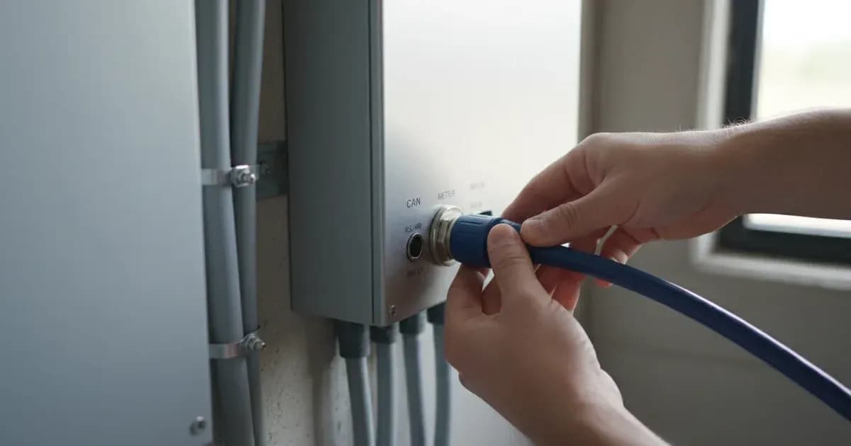
This intelligent interaction ensures the battery operates within its safe limits, prolonging its service life and maintaining system efficiency. For the Solis S6, this typically involves a CAN (Controller Area Network) communication port.
The Role of CAN Port Wiring and Battery Model Selection
System Component / Step | Technical Requirement & Specification | Functional / Operational Objective |
|---|---|---|
CAN Bus Wiring | Shielded twisted-pair cabling connected to dedicated CAN port | High-speed, noise-free telemetry between inverter and battery BMS |
Battery Selection | Model selected from official compatibility matrix | Enables intelligent closed-loop control over open-loop voltage mode |
CT Clamp Sensing | Arrow oriented toward household loads (away from grid incomer) | Prevents inverted readings and false negative power flow calculations |
Chassis Earthing | Inverter chassis and battery metal enclosure bonded to main earth terminal | Eliminates shock hazards and ensures compliance with electrical safety standards |
Inverter Configuration | Closed-loop BMS protocol and parameter pairing via menu | Dynamically regulates charge/discharge rates to protect cell lifespan |
The CAN port facilitates the high-speed, reliable data exchange between the Solis S6 inverter and the battery's BMS. Correct wiring of this port is paramount. official technical guidance indicates that maintaining "shielded twisted-pair cabling and verify proper RS485 communication baud rate settings" is a general requirement for communication, which applies to robust data links like CAN.
Battery model selection is equally critical. Not all batteries are compatible with the Solis S6's closed-loop communication. Manufacturers provide specific lists of compatible battery models and the required communication protocols (e.g., CAN, RS485). Selecting a battery not on this list may prevent closed-loop operation, forcing the inverter to operate in a less efficient, voltage-based open-loop mode.
The specific wiring diagrams, pinouts, and configuration steps for connecting a compatible battery's BMS to the Solis S6 CAN port are detailed in the Solis S6 installation manual and the battery manufacturer's documentation. These documents also specify any necessary dip switch settings or software configurations within the inverter.
What You Can Check Yourself, and What You Cannot
As a homeowner, you can perform basic visual checks and ensure the system is operating as expected through monitoring platforms like SolisCloud. However, any physical wiring, configuration changes, or troubleshooting beyond simple resets should be left to accredited professionals.
What you can check:
- Visual inspection: Ensure all cables appear securely connected and undamaged.
- Monitoring data: Use SolisCloud to observe battery state of charge, power flow, and system status. Anomalies here might indicate an issue.
- Error codes: Note any error codes displayed on the inverter or in SolisCloud. These can provide initial clues for an accredited installer.
What you cannot check or change yourself:
- CAN port wiring: Modifying or re-wiring the CAN port connections. This requires specialised tools and knowledge to ensure "shielded twisted-pair cabling" is correctly terminated and connected.
- Inverter settings: Changing any inverter settings related to BMS communication, battery type, or charge/discharge parameters. Incorrect settings can damage the battery or inverter.
- CT clamp installation: official documentation notes that "negative power flow during high household consumption indicates inverted CT clamp installation." Correcting this requires "complete AC circuit isolation and lock-out before installing CT clamps on live busbars," which is a task for a qualified electrician.
- Earthing and bonding: Ensuring "inverter chassis ground and battery metal enclosure to the main installation earthing terminal" is a fundamental safety requirement that must be verified by an accredited professional during installation.
Changing inverter settings yourself, particularly those related to grid protection or battery management, can breach your connection agreement with the Distribution Network Operator (grid operator) and void warranties.
General Safety and Compliance Considerations
The installation of a Solis S6 hybrid inverter, especially when integrating a battery system with BMS communication, must comply with stringent safety and regulatory standards. official documentation highlights several general requirements that apply to such installations in Pakistan:
- Regulatory Compliance: The system must comply with "international microgeneration safety and grid protection standards." In Pakistan, grid-tied installations must comply with NEPRA's net metering regulations and your local DISCO's interconnection requirements.
- Earthing: "Bond inverter chassis ground and battery metal enclosure to the main installation earthing terminal." This is a critical safety measure to prevent electric shock.
- CT Clamp Installation: "Install Current Transformer clamps with arrows pointing towards the household loads away from the grid incomer." Incorrect CT clamp orientation can lead to inaccurate power measurements and incorrect inverter operation.
- Accreditation: Installation should be carried out by a certified installer, and grid export requires DISCO approval and NEPRA-compliant net metering documentation.
These general principles underscore the importance of professional installation and commissioning. An accredited installer will ensure that all wiring, earthing, and communication settings are correctly configured, and that the system is safe and compliant with all local regulations.
What the Published Sources Do Not Tell You
The provided official documentation offers general principles for solar installations and compliance in Pakistan but does not contain specific technical details for configuring the Solis S6 hybrid inverter's BMS closed-loop CAN port, specific wiring diagrams, compatible battery models, or SolisCloud integration steps.
- Specific CAN Pinouts: The exact pin assignments for the Solis S6 CAN port are not provided. These are crucial for correct wiring.
- Battery Compatibility Matrix: A list of specific battery models that are compatible with the Solis S6's BMS closed-loop communication is absent.
- Inverter Menu Navigation: The step-by-step process for configuring BMS communication within the Solis S6 inverter's menu system is not detailed.
- SolisCloud Configuration: Specific instructions for integrating the BMS data or making adjustments via the SolisCloud platform are not included.
- RS485 Baud Rate Settings: While RS485 baud rate settings are mentioned as a general communication requirement, the specific rate for the Solis S6 or compatible batteries is not provided.
For these critical specifics, you must consult the official Solis S6 hybrid inverter installation and user manuals, as well as the technical documentation provided by your chosen battery manufacturer. These documents will contain the precise information required for safe and effective configuration.
Add a battery at a surveyed price
Installers quote supply and fitting of the battery on this page for your existing or new system.
How this pays for the site: installers pay SolarNevs a fixed introduction fee when we pass them a genuine enquiry. They cannot pay to appear higher, and our surveyed prices are published before any introduction. You can also take our dated price tables straight to any installer.
Frequently asked questions
What are the primary technical requirements for solis s6 hybrid inverter bms closed loop can wiring guide?
Key requirements include compliance with local grid codes, correct equipment certification, and proper electrical isolation.
Who is authorized to install and inspect solis s6 hybrid inverter bms closed loop can wiring guide?
All high-voltage DC, AC grid tie-in, and switchboard modifications must be performed by a qualified, accredited electrical professional.
How is export power limited in solis s6 hybrid inverter bms closed loop can wiring guide?
Export limiting is achieved using certified bidirectional smart meters or power sensors providing dynamic feedback to the inverter system.
References
Related guides
More from what to buy — and how not to get cheated.