Victron Cerbo GX: BMS-CAN & VE.CAN Port Setup Guide
Updated 6 September 2026 · By SolarNevs Research Desk, Dealer surveys + verified sources · 1 source · Method ↗
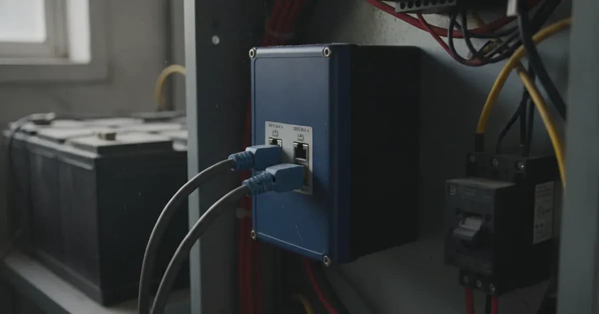
Key Takeaways
- The Victron Cerbo GX features independent VE.Can (250 kbit/s default) and BMS-Can (500 kbit/s) CAN-bus interfaces.
- Every CAN-bus chain requires RJ45 terminator resistors (2 pcs supplied) installed at both physical ends of the network.
- Closed-loop communication with managed lithium batteries (e.g. Pylontech, BYD, Discover) connects via the BMS-Can port.
- Enabling DVCC (Distributed Voltage and Current Control) centrally synchronises charging algorithms across MPPT solar chargers and inverters.
- DVCC incorporates Shared Voltage Sense (SVS), Shared Temperature Sense (STS), and Shared Current Sense (SCS).
CAN-Bus Architecture & Baud Rate Profiles
Under Section 5.5 of the Cerbo GX manual, the device integrates dual CAN-bus interfaces designed to segregate internal Victron hardware communications from third-party battery management systems:
CAN Port | Default Baud Rate | Typical Connected Hardware | Network Profile |
|---|---|---|---|
VE.Can Port | 250 kbit/s | SmartSolar MPPTs, Inverter RS, Multi RS, Lynx Shunt | Standard Victron VE.Can protocol |
BMS-Can Port | 500 kbit/s | Pylontech, BYD, Freedomwon, Discover AES | CAN-bus BMS protocol (500 kbit/s or 250 kbit/s) |
Bus Termination | Essential | Requires RJ45 terminators (2 pcs supplied) at both bus ends | Prevents bus error frames |
Distributed Voltage & Current Control (DVCC)
Under Chapter 12, Distributed Voltage and Current Control (DVCC) converts the Cerbo GX into a centralized system controller:
- Centralised Charge Control: When a managed lithium battery is detected on BMS-Can, DVCC automatically configures voltage setpoints and maximum charge current limits (CCL).
- Solar Absorption Synchronization: Overrides individual MPPT internal charge curves, ensuring all charge controllers transition to float simultaneously.
- Shared Voltage Sense (SVS): Broadcasts battery terminal voltage to all connected chargers, eliminating DC cable resistance measurement errors.
- Shared Temperature & Current Sense: Utilises Shared Temperature Sense (STS) and Shared Current Sense (SCS) from the battery monitor to optimize power distribution.
Battery BMS Integration Best Practices
To establish reliable closed-loop communication:
- Connect the manufacturer-supplied CAN cable between the battery BMS CAN port and the Cerbo GX BMS-Can socket.
- Insert an RJ45 terminator into the second BMS-Can port on the Cerbo GX, and into the battery bank end-of-line port.
- Navigate to Venus OS Settings -> Services -> CAN-profile and confirm the BMS-Can port speed matches the battery requirement (500 kbit/s or 250 kbit/s).
Add a battery at a surveyed price
Installers quote supply and fitting of the battery on this page for your existing or new system.
How this pays for the site: installers pay SolarNevs a fixed introduction fee when we pass them a genuine enquiry. They cannot pay to appear higher, and our surveyed prices are published before any introduction. You can also take our dated price tables straight to any installer.
Frequently asked questions
What are the default baud rates for VE.Can and BMS-Can ports on the Cerbo GX?
The VE.Can port operates at **250 kbit/s** (default for Victron products), while the BMS-Can port operates at **500 kbit/s** (or **250 kbit/s** for specific CAN-bus BMS profiles) (August 2026).
Why are RJ45 terminators required on Cerbo GX CAN-bus networks?
CAN-bus networks require RJ45 terminator resistors (2 pieces included with the Cerbo GX) installed in the unused RJ45 sockets at both physical ends of the bus to prevent signal reflections (August 2026).
What is Distributed Voltage and Current Control (DVCC)?
DVCC is an advanced control algorithm that allows the Cerbo GX to centrally coordinate charging parameters between CAN-bus lithium batteries, solar charge controllers, and inverters (August 2026).
What sensing functions are managed by DVCC?
DVCC coordinates Shared Voltage Sense (SVS), Shared Temperature Sense (STS), and Shared Current Sense (SCS) across all connected Victron components (August 2026).
References
- Victron Energy: Cerbo GX Manual — accessed 31 August 2026
Related guides
More from what to buy — and how not to get cheated.