Victron MultiPlus Parallel and Three-Phase System Wiring Rules
Updated 8 September 2026 · By SolarNevs Research Desk, Dealer surveys + verified sources · 4 sources · Method ↗
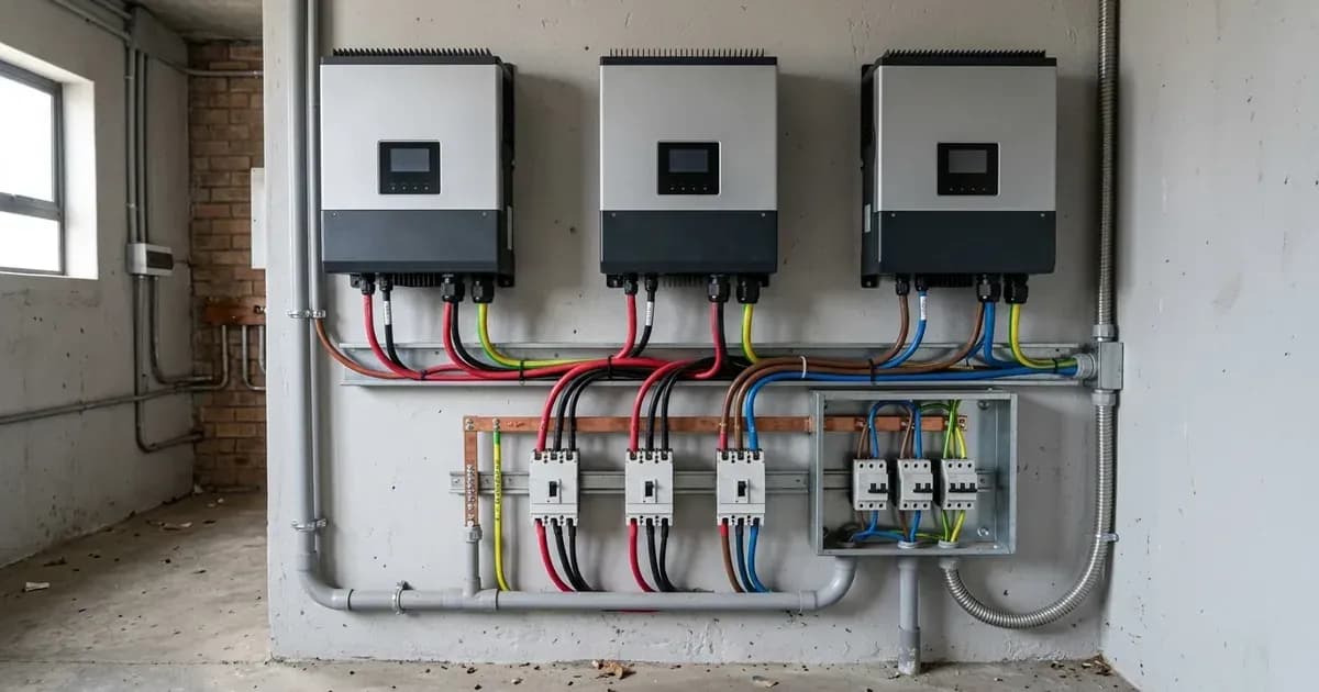
Victron Energy MultiPlus, MultiPlus-II, and Quattro inverter/chargers are designed to operate in parallel or three-phase configurations, allowing for increased power output and balanced load distribution. Proper installation, especially regarding wiring and communication, is critical for the safety, reliability, and performance of these advanced systems.
This guide details the essential engineering and installation rules for setting up Victron MultiPlus and Quattro inverter/chargers in parallel and three-phase configurations.
Understanding Victron Multi-Unit Systems
Victron Energy manufactures MultiPlus, MultiPlus-II, and Quattro VE.Bus inverter/chargers, which are central to Victron power systems. These devices support parallel operation to increase total power and three-phase configurations for balanced load distribution across phases. The system relies on a Master/Slave VE.Bus architecture for coordinated operation.
Critical DC Wiring Rules
Correct DC wiring is fundamental for stable parallel and three-phase Victron systems. Inconsistent wiring can lead to circulating currents, reduced performance, and potential equipment damage.
Single DC Bus and Symmetrical Connections
All DC connections on every Multi/Quattro unit and on every battery must connect to a single DC bus. For units operating in parallel, both the DC and AC wiring must be symmetrical per phase. This means using the same length, type, and cross-section of cable to every unit in that phase.
To facilitate symmetrical wiring, use a bus-bar or power-post before and after the inverter/chargers. When making connections, apply the same torque on all terminals to ensure consistent contact and resistance.
DC Fusing
Each unit requires individual fusing for DC. It is important to use the same type of fuse on each unit to maintain consistent resistance across the parallel paths.
Safety Warning: Working with high-current DC connections can be hazardous. Always kill power first by disconnecting the battery bank and any other DC sources. Use insulated tools to prevent accidental short circuits, as a spanner across a battery bank can short hundreds of amps.
Essential AC Wiring Rules
Similar to DC wiring, AC connections in parallel and three-phase systems demand precision to ensure balanced current sharing and prevent issues.
Symmetrical AC Connections
For units in parallel, the AC wiring needs to be symmetrical per phase, using the same length, type, and cross-section of cable to every unit in the phase. A bus-bar or power-post can help achieve this symmetrical wiring before and after the inverter/chargers.
Avoid over-dimensioning the AC cabling, as extra thick cabling can negatively affect current distribution among units.
AC Fusing
Each unit needs to be fused individually for AC. Consider using mechanically connected AC fuses, so that if one trips, they all trip, providing a clear fault indication.
Three-Phase Configuration
Victron products are designed for a star (Y) type three-phase configuration, which requires a distributed neutral where all neutrals are connected. Delta (Δ) configurations are not supported.
Be aware of phase rotation between the inverter and the AC input. If the wiring differs from the system's programming, the system will not accept mains input.
Safety Warning: Always kill power to the AC input and output circuits by opening all relevant AC breakers before working on AC wiring. Verify isolation with a multimeter.
VE.Bus Communication Wiring (RJ45 Daisy-Chain)
The VE.Bus communication network is crucial for the coordinated operation of parallel and three-phase systems. Incorrect cabling can lead to communication errors and system instability.
Daisy-Chain Topology
All units must be daisy-chained using a VE.Bus cable (RJ-45 Cat5 or better). The sequence for daisy chaining units is not important. Do not use terminators in the VE.Bus network.
The optimal arrangement for the VE.Bus network is a single RJ45 cable link from the GX device to the first VE.Bus inverter/charger, and then daisy-chain to subsequent VE.Bus inverter/chargers if they exist. The end-ports of the VE.Bus should be left open or blanked out with no connection made.
Cable Quality and Management
Use industrially made network cabling; self-crimped RJ45 cables are a known cause of various communication errors. Maintain separation between power and communication cables, as bundling them together should always be avoided. Minimise cable lengths where possible and avoid bundling or coiling excess cable, as longer runs can weaken the signal and increase noise.
DC solar cables are the most likely to cause interference, followed by AC cables, then DC battery cables. Ferrite core noise suppressing cable clips can help filter out noise and should be installed on GX cables.
Sensor Wiring in Multi-Unit Systems
For accurate system operation, temperature and voltage sensing must be correctly configured.
Temperature Sensor
The temperature sensor can be wired to any unit in the system. For large battery banks, it is possible to wire multiple temperature sensors. The system will use the one with the highest temperature to determine the temperature compensation.
Voltage Sense
Wire the voltage sense on the master of L1. All other units ignore their voltage sense input.
Loss of Mains (LOM) Detection
Loss of Mains (LOM) detection is an automatic process that detects a loss of the mains/network/grid supply. Its purpose is to ensure safety by opening the back-feed relay, preventing the inverter from feeding power into a de-energized grid (anti-islanding).
How LOM Works
The inverter/charger constantly tries to shift the AC frequency. If connected to a stable grid, it cannot shift the frequency, indicating mains presence. If mains is lost, the inverter can shift frequency at will, triggering LOM detection.
LOM Types and Considerations
- LOM Type A: This is the strongest form of LOM detection, resulting in the quickest detection time. It requires a low impedance grid connection and does not work with generators.
- LOM Type B: This type has a softer approach and a slightly longer detection time. It is approved for most Multi/grid code combinations and works better with generators or high impedance mains connections.
A high-impedance connection (e.g., to a generator or long extension cable) can make the LOM algorithm unstable, potentially causing high currents and unit shutdown due to overload. A weak utility connection can also cause continuous frequency shifts, activating a safety mechanism that temporarily disables feed-in.
Disabling LOM
LOM can be temporarily disabled in VEConfigure on the Grid tab by changing the LOM detection setting to "None." This requires a password from your dealer.
Critical Safety Warning: Disabling LOM on an input connected to the grid is only allowed when other external safety equipment, such as an anti-islanding safety device (e.g., Ziehl), is installed. This is a critical safety issue and must comply with local regulations.
There is no regulatory need to install external anti-islanding equipment when disabling LOM in combination with a generator, but clear warnings and disconnection procedures must be in place for installers. ESS systems require LOM for safety and regulatory compliance, even if feed-back is disabled.
Some bigger or better quality generators will be able to work with LOM Type B. If your generator is smaller than the recommended size for your inverter/charger, you will need to adjust the settings on the inverter/charger and reduce the AC input current limit, and/or a DC charge current limit to prevent overloading the generator. Activating the "Weak AC input" function in the Charger tab enables the MultiPlus to charge under practically any condition, though it degrades the input power factor.
Common VE.Bus Errors in Multi-Unit Systems
VE.Bus Error Code | Error Description & Operational State | Diagnostic Cause & Resolution Step |
|---|---|---|
Error 1 | Phase shutdown cascade | Failing phase tripped; inspect LEDs for Overload, Low Battery, or Temperature |
Error 3 | Device count mismatch | System found unexpected device count; check configuration, cables, and DC fuses |
Error 4 | No other device found | Master cannot detect slave units; check RJ45 patch leads and replace self-crimped cables |
Error 5 | Overvoltage on AC out | Slave AC output wiring disconnected, loose, or improperly connected |
Error 17 | Phase master missing | Slave communication timeout with phase master; inspect VE.Bus daisy-chain bus |
Several VE.Bus error codes are specifically relevant to parallel and three-phase systems, often indicating communication or configuration issues.
- Error 1: Device is switched off because one of the other phases in the system has switched off. Identify the failing phase (the one not showing Error 1) and check its LEDs for Overload, Low battery, or Temperature alarms. On a GX device, check the alarm status for each phase.
- Error 3: Not all, or more than, the expected devices were found in the system. Solve the cause for VE.Bus Error 1 if it preceded this error. Ensure all VE.Bus devices are configured as one system. Check communication cables for faults, using commercial patch leads, and check for blown DC fuses in any unit.
- Error 4: No other device found. The master device is configured for a parallel, split-phase, or three-phase system but cannot find other devices on the bus. This can be temporary during a system restart. Check communication cables for faults, avoiding self-made cables.
- Error 5: Overvoltage on AC out. This problem can occur when the AC wiring of one of the slave units is not connected properly, or not connected at all.
- Error 17: Phase master missing. This error shows on slave units only when communication with the phase-master has timed out.
To prevent many communication-related errors, ensure you use industrially made network cabling instead of self-crimped RJ45 cables.
Conclusion
Implementing Victron MultiPlus and Quattro inverter/chargers in parallel or three-phase systems requires meticulous attention to DC, AC, and communication wiring. Adhering to these rules ensures the system operates efficiently, reliably, and safely, providing the intended power and functionality.
Frequently asked questions
What is the main purpose of Victron MultiPlus Parallel and Three-Phase System Wiring Rules?
It provides official Victron Energy configuration rules, technical parameters, and step-by-step troubleshooting procedures.
How do I resolve issues related to victron parallel wiring rules?
Follow the documented verification steps, check wiring and firmware, and ensure all parameters match official Victron specifications.
References
- Victron Support: Ve.Bus - Manual Parallel And Three Phase Systems — accessed 27 August 2026
- Victron Support: Venus-Os - Remote Ve.Bus Firmware Updates — accessed 27 August 2026
- Victron Support: Ve.Bus - Ve.Bus Error Codes — accessed 27 August 2026
- Victron Support: Ve.Bus - Ve.Bus Network Interference — accessed 27 August 2026
Related guides
More from sizing, net billing & installation.