Growatt Smart Meter Wiring and Zero Export Guide
Updated 8 September 2026 · By SolarNevs Research Desk, Dealer surveys + verified sources · 1 source · Method ↗
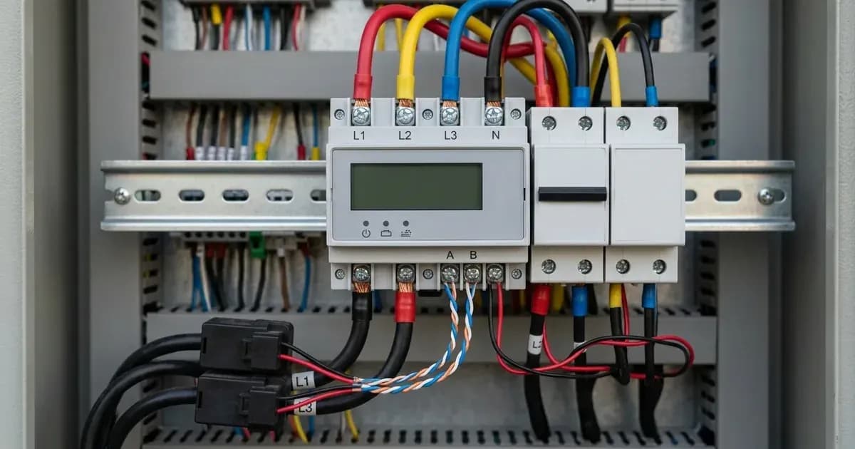
This guide details the definitive wiring and configuration procedures for Growatt inverters when paired with Eastron smart meters (SPM-E and SDM630-Modbus) to achieve zero export. We will cover RS485 communication terminal wiring, correct CT clamp orientation, troubleshooting for reverse CT readings, and programming the Export Limit via ShinePhone.
Understanding Growatt Zero Export
Growatt inverters, manufactured by Growatt New Energy, can be configured to prevent excess solar power from being exported to the grid. This "zero export" functionality relies on a smart meter to accurately measure grid power flow. The smart meter communicates with the inverter, allowing it to dynamically adjust its output to match household consumption. This setup is compatible with residential single-phase and commercial three-phase energy storage installations globally.
Required Smart Meters
Smart Meter Model | Grid Phase Compatibility | RS485 Wiring & Interface | CT Sensor Alignment & Rule |
|---|---|---|---|
Eastron SPM-E | Single-Phase (1-Phase) | Shielded twisted-pair to RS485-A & RS485-B | Arrow points toward household loads on main incoming grid line |
Eastron SDM630-Modbus | Three-Phase (3-Phase) | Shielded twisted-pair to RS485-A & RS485-B | 3x CT arrows point toward household loads; L1/L2/L3 phases strictly matched |
Growatt inverters utilize specific Eastron smart meters for this functionality:
- Eastron SPM-E: For single-phase installations.
- Eastron SDM630-Modbus: For three-phase installations.
These smart meters communicate with Growatt hybrid and string inverters via dedicated RS485 terminal connections.
Safety First: Before You Begin Any Wiring
Working with electrical systems carries inherent risks. Always prioritize safety to prevent injury or damage to equipment.
Isolate Power: Before performing any wiring, it is critical to de-energize the main distribution board and isolate all circuit breakers. This includes both AC and DC isolators.
Capacitor Discharge: After switching off all AC and DC isolators, wait at least 5 minutes before opening inverter wiring compartments. This allows internal capacitors to safely discharge.
Wiring the Smart Meter
Correct installation and wiring of the smart meter are crucial for accurate power measurement and effective zero export control.
1. Smart Meter Physical Placement
The smart meter must be installed at the main grid connection point before any distribution sub-circuits. This ensures it measures the total power flowing to and from the grid for the entire premises.
2. RS485 Communication Wiring
The smart meter communicates with the Growatt inverter via an RS485 connection.
Procedure:
- Ensure all power is isolated as per the safety instructions above.
- Connect a communication cable to the RS485-A and RS485-B terminals on the smart energy meter.
- Use a shielded twisted pair cable for this connection to minimize interference.
- Connect the other end of this cable to the corresponding RS485-A and RS485-B terminals on your Growatt inverter. Refer to your specific inverter's manual for exact terminal locations.
3. CT Clamp Installation and Orientation
Current Transformers (CT clamps) measure the current flowing through the grid lines. Their orientation is critical.
Procedure:
- Ensure all power is isolated.
- Position the external current transformers on the incoming grid phases.
- Crucially, ensure the arrows on the CT clamps are pointing towards the household loads. This indicates the direction of current flow from the grid into your property.
- In three-phase installations, verify that voltage phases (L1, L2, L3) correspond strictly to the respective CT clamp phases.
Configuring Zero Export in ShinePhone/Inverter
Once the smart meter is correctly wired, you need to configure the inverter for zero export.
Procedure:
- Access the inverter settings via the ShinePhone app or the inverter's OLED menu.
- Navigate to the "Export Limit" setting.
- Enable "Export Limit".
- Set the export power limit to 0 Watts.
This configuration instructs the inverter to limit its output so that no power is sent back to the grid.
Troubleshooting Common Issues
Reverse CT Clamp Reading
A common issue during smart meter installation is incorrect CT clamp orientation.
Diagnostic Indicator: If the smart meter power reading shows negative during grid import, this indicates that the CT clamp is installed in reverse. Grid import should always show as a positive power flow from the grid.
Solution: To correct this, reverse the CT clamp orientation on the main line. Ensure the arrow on the CT clamp points towards the household loads.
Verifying Operation
After installation and configuration, you can verify the system's operation. Accurate meter connection enables ShineServer to display real-time household consumption and solar self-consumption, confirming that your zero export system is functioning as intended.
Frequently asked questions
What are the essential requirements for growatt smart meter wiring and zero export guide?
Verify system specifications, local regulations, and standard installation safety procedures prior to commissioning.
How do I ensure regulatory compliance?
Ensure all equipment is approved on relevant regulatory registries and installed by accredited certified professionals.
References
- Growatt Monitoring App (ShinePhone) — official product page — accessed 27 August 2026
Related guides
More from sizing, net billing & installation.