Victron GX Tank 140: Setup & Analogue Sensor Guide
Updated 6 September 2026 · By SolarNevs Research Desk, Dealer surveys + verified sources · 1 source · Method ↗
Key Takeaways
- The Victron GX Tank 140 Interfaces with either 4 to 20mA or 0 to 10V tank level sensors (including a combination of both) across 4 analogue channels.
- Connects directly to Cerbo GX, Ekrano GX, or Venus GX controllers via a Connection to the GX Device via USB interface with a GX Tank 140 unit with non-detachable 1.5 meter cable.
- Channel 1 and 2 use a fused power source from the V in connection for sensor excitation from an external DC supply.
- Channel 3 and 4 use an integrated 24V power source for sensor excitation, which is powered via the USB interface, eliminating auxiliary power bricks.
- The integrated 24V power source simplifies the installation/wiring process, as no additional power source is required for standard 2-wire 4-20mA current loop senders.
- Features a Configurable input range, for example to connect a 0 to 5V sensor for customized pressure and level transmitters.
- Includes a Configurable averaging filter (1 to 60 seconds) to dampen the effect of fluid movement in mobile marine and RV tanks.
- Monitors signal health: In case the measured voltage/currents exceeds the limits (voltage: >10V, current: <4mA or >20mA) an error will be triggered.
- Protected by a Five year limited warranty This limited warranty covers defects in materials and workmanship in this product, and lasts for five years from the date of original purchase of this product.
Module Overview & Channel Power Architecture
The Victron GX Tank 140 expands Venus OS system controllers by adding 4 precision analogue sensor input channels. It allows commercial solar, marine, and off-grid facilities to monitor fuel, fresh water, greywater, and industrial fluid levels alongside electrical storage metrics.
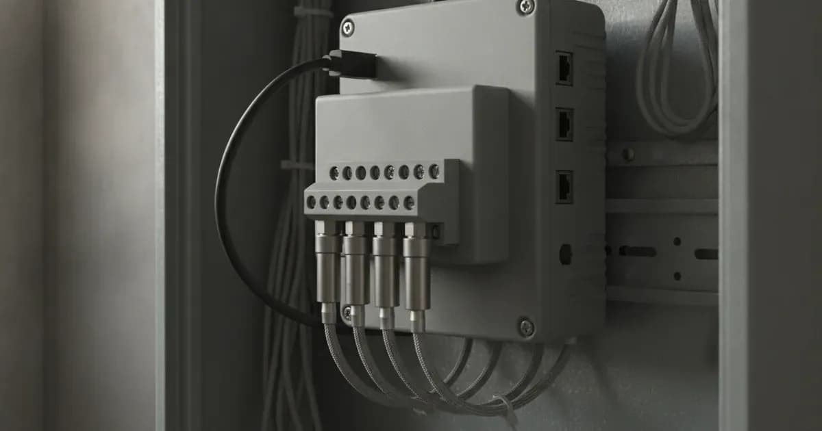
The Victron GX Tank 140 provides a 4-channel analogue interface (4 to 20mA / 0 to 10VDC / 0 to 5VDC) with a non-detachable 1.5m USB cable for plug-and-play connection to GX devices:
- Channels 1 & 2 (External Supply): Fused V in Excitation, Connects 0-10V / 4-20mA Senders, Pluggable Terminal Blocks.
- Channels 3 & 4 (USB 24V DC): Integrated 24V Power, No Extra Power Supply Req., Powers 2-Wire 4-20mA Loops.
Sensor Excitation Setup
- Channels 1 & 2 (V in Fused Power): Channel 1 and 2 use a fused power source from the V in connection for sensor excitation. When powering 12V or 24V senders from the main battery bank, connect external DC positive to the V in terminal.
- Channels 3 & 4 (Integrated 24V Supply): Channel 3 and 4 use an integrated 24V power source for sensor excitation, which is powered via the USB interface. Because The integrated 24V power source simplifies the installation/wiring process, as no additional power source is required, these channels are ideal for 2-wire industrial 4-20mA hydrostatic pressure senders.
Sensor Wiring & Voltage / Current Configuration
The GX Tank 140 terminal blocks accommodate both voltage-output and current-loop transducers:
Sensor Type | Terminal Wiring Configuration | Operating Voltage / Current Limits | Application |
|---|---|---|---|
Current Output (4-20mA) | Sourced via Ch 3/4 (24V Out & In) or Ch 1/2 (V in & In) | 4mA (empty) to 20mA (full) | Submersible hydrostatic pressure transmitters |
Voltage Output (0-10V) | Power from V in; Signal to In; Ground to GND | 0V (empty) to 10V (full) | Industrial ultrasonic and resistive senders |
Voltage Output (0-5V) | Power from V in; Signal to In; Ground to GND | Configurable input range, for example to connect a 0 to 5V sensor | Automotive and ratiometric voltage senders |
Venus OS Damping & Fault Diagnostics
Configuring the GX Tank 140 in Venus OS (Settings -> Analog inputs -> Tank inputs) provides software-level tuning and automated alarm triggers:
- Fluid Movement Damping: Sloshing in marine and mobile vehicle tanks causes erratic level fluctuations. Activating the Configurable averaging filter (1 to 60 seconds) to dampen the effect of fluid movement provides smooth, stabilized volume readings.
- Fault Threshold Alarms: In case the measured voltage/currents exceeds the limits (voltage: >10V, current: <4mA or >20mA) an error will be triggered. An open-circuit wire fault drops the current below 4mA, immediately alerting the operator.
- Tripped Fuse Behaviour: In current-sensor setups, The internal self-resetting fuse has a permanent current flow of ~11 to 13mA when tripped and the GX Tank 140 cannot detect this state as a fault, resulting in a stuck reading around 40% to 55%. If this occurs, inspect field wiring for short circuits.
- Warranty Backing: The unit includes a Five year limited warranty This limited warranty covers defects in materials and workmanship in this product, and lasts for five years from the date of original purchase of this product.
Add a battery at a surveyed price
Installers quote supply and fitting of the battery on this page for your existing or new system.
How this pays for the site: installers pay SolarNevs a fixed introduction fee when we pass them a genuine enquiry. They cannot pay to appear higher, and our surveyed prices are published before any introduction. You can also take our dated price tables straight to any installer.
Frequently asked questions
What types of tank level sensors are compatible with the Victron GX Tank 140?
The GX Tank 140 **Interfaces with either 4 to 20mA or 0 to 10V tank level sensors (including a combination of both)** across its 4 independent channels (August 2026).
How is the GX Tank 140 connected to the GX device and powered?
It features a **Connection to the GX Device via USB interface** using a **GX Tank 140 unit with non-detachable 1.5** meter USB lead (August 2026).
How does the GX Tank 140 provide power excitation for connected sensors?
Channel 1 and 2 use a fused power source from the V in connection for sensor excitation, whereas **Channel 3 and 4 use an integrated 24V power source for sensor excitation, which is powered via the USB interface** (August 2026).
What signal thresholds trigger sensor fault alarms on the GX Tank 140?
An alarm triggers **In case the measured voltage/currents exceeds the limits (voltage: >10V, current: <4mA or >20mA)** (August 2026).
References
- Victron Energy: GX Tank 140 Manual — accessed 31 August 2026
Related guides
More from what to buy — and how not to get cheated.