Victron Et112 And Et340 Energy Meter Modbus Wiring Guide
Updated 15 September 2026 · By SolarNevs Research Desk, Dealer surveys + verified sources · 4 sources · Method ↗
Key Takeaways
- Victron ET112 (single-phase) and ET340 (three-phase) meters integrate via RS485 Modbus RTU.
- Correct wiring polarity for the RS485 Orange (Data+ / A) and Yellow (Data- / B) wires is crucial for communication.
- Installation requires complete AC circuit isolation and proper earthing bonding for safety.
- Negative power flow readings often indicate an inverted Current Transformer (CT) clamp installation, requiring reorientation.
What are Victron ET112 and ET340 Energy Meters?
The Victron ET112 and ET340 are energy meters designed to measure AC power flow in solar photovoltaic (PV) and energy storage systems. The ET112 is a single-phase meter, capable of direct in-line current measurement up to 100A. The ET340 is a three-phase meter, handling direct measurement up to 65A per phase.
These meters are essential components in Victron Energy systems, particularly for managing grid-tied installations. They provide real-time data on grid import and export, allowing the Victron GX device (such as a Cerbo GX) to make informed decisions about battery charging, discharging, and overall power management. The meters communicate with the GX device using the Modbus RTU protocol over an RS485 connection.
How do these meters enable zero export?
Zero export, or zero injection, is a common requirement in many grid-tied solar PV installations. It means that no excess solar power is fed back into the public electricity grid. Instead, any surplus power is either used by local loads or stored in a battery system.
The Victron ET112 and ET340 meters play a critical role in achieving dynamic zero export control. Positioned at the grid incomer point of your property, they continuously monitor the power flow between your premises and the grid. This real-time data is sent to the Victron GX device. The GX device, running Venus OS, uses this information to instruct the inverter/charger (e.g., a MultiPlus or Quattro) to adjust its output.
For example, if the meter detects that your solar panels are generating more power than your home is consuming, and your batteries are full, the GX device will tell the inverter to reduce its output or divert power to other loads if available. Conversely, if your home needs more power than the solar panels are generating, the system will draw power from the battery or the grid as needed. This dynamic management ensures that power flow to the grid is minimised or eliminated, complying with local grid regulations. The system's ability to manage power flow is based on the principle that the "ESS assistant dynamically manages battery charge and discharge based on grid tariffs and load."
Wiring the ET112/ET340 to your Victron GX Device: A Step-by-Step Guide
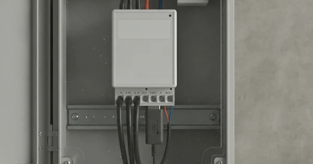
Correct wiring is paramount for the reliable operation and safety of your Victron energy meter. The meters connect to a Victron GX device via a Victron RS485-to-USB Interface Cable.
Key Installation Steps
Parameter | What it means | What to do |
|---|---|---|
Safe Panel Isolation Protocols | Before any work, ensure the electrical panel is de-energised. | "Ensure complete AC circuit isolation and lock-out before installing CT clamps on live busbars." This is a critical safety step to prevent electric shock. |
Chassis Protective Earthing Bonding | Proper earthing protects against electrical faults. | "Bond inverter chassis ground and battery metal enclosure to the main installation earthing terminal." This ensures all metallic enclosures are safely earthed. |
Incomer Grid Connection Point Placement | The meter must be correctly positioned to monitor grid flow. | Install the meter at the main grid incomer point. This allows the system to accurately measure power import and export for zero export control. |
Current Transformer (CT) Clamp Installation | CT clamps measure current flow. | "Install Current Transformer clamps with arrows pointing towards the household loads away from the grid incomer." Incorrect orientation will lead to inaccurate readings. |
RS485 to USB Interface Cable Connection | This cable facilitates communication between the meter and GX device. | Connect the Victron RS485-to-USB Interface Cable to the meter's RS485 terminals. Ensure the Orange (Data+ / A) and Yellow (Data- / B) wires are connected with correct polarity. |
Twisted Pair Shielded Cabling Requirement | Shielded cables prevent interference. | "Maintain shielded twisted-pair cabling" for the RS485 connection. This minimises electromagnetic interference and ensures reliable communication. |
Configuring the Energy Meter in Venus OS
Once the physical wiring is complete, the Victron GX device, running Venus OS, should automatically detect the connected energy meter.
- Automatic Meter Discovery: The "GX Device Automatic Meter Discovery" feature in Venus OS simplifies the setup process. Connect the RS485-to-USB cable to a USB port on your GX device.
- Verify Communication: Navigate through the Venus OS menu on your GX device (or via the Victron Remote Console) to the 'Settings' -> 'Energy Meters' section. You should see the newly connected ET112 or ET340 listed.
- Role Assignment: Assign the meter its correct role, typically 'Grid meter'. This tells Venus OS that this meter is monitoring the main grid connection point.
- Phase Allocation (for ET340): For three-phase ET340 meters, ensure the 'Phase Allocation Configuration in Venus OS' matches your electrical installation. This ensures that each phase's data is correctly interpreted by the system.
- Zero Export Configuration: Within Venus OS, confirm that the ESS (Energy Storage System) assistant is configured for 'Optimised (with BatteryLife)' or 'Optimised (without BatteryLife)' mode, and that the 'Grid setpoint' is set to 0W for zero export.
Troubleshooting Common Communication Issues
Even with careful installation, issues can arise. Here are common problems and how to address them:
- No Meter Detected: If your GX device does not detect the meter, first check the physical USB connection. Then, verify the RS485 wiring. The "In Victron ET112/ET340 setups, verify that the RS485 Orange (Data+ / A) and Yellow (Data- / B) wires are terminated in the correct polarity." Incorrect polarity is a frequent cause of communication failure.
- Inaccurate Readings / Negative Power Flow: If the meter reports unexpected values, especially "Negative power flow during high household consumption," it "indicates inverted CT clamp installation." The arrows on the CT clamps must point away from the grid and towards the loads. Reversing the clamps will correct the reading.
- Intermittent Communication: This can often be caused by electrical noise or poor cabling. Ensure you have used "Twisted Pair Shielded Cabling" for the RS485 connection to minimise interference. Also, "verify proper RS485 communication baud rate settings" in Venus OS, though typically this is auto-detected.
- Meter Not Responding: Check the meter's power supply. Although the meters are direct measurement, they require auxiliary power. Ensure all connections are secure.
Safety Considerations for Energy Meter Installation
Working with electrical systems carries inherent risks. Always prioritise safety.
- Isolation: Before touching any wiring or installing Current Transformers, "Ensure complete AC circuit isolation and lock-out before installing CT clamps on live busbars." This means turning off the main circuit breaker and securing it to prevent accidental re-energisation.
- Earthing: "Bond inverter chassis ground and battery metal enclosure to the main installation earthing terminal." Proper earthing is vital to prevent electric shock in the event of a fault.
- Qualified Personnel: Electrical work should ideally be performed by a qualified and accredited electrician. This ensures compliance with local regulations and safety standards.
- Compliance: For microgeneration installations in Great Britain, "An MCS Certificate is required to access export tariffs and verify building regulations compliance." This certification ensures that the installation meets recognised industry standards for safety and performance.
What the published sources do not tell you
While product manuals and certification bodies like MCS provide essential information, some practical details are often not explicitly stated or vary by specific installation. For instance, the exact length limitations for RS485 cabling can depend on the cable quality and environment, though shielded twisted pair is always recommended for longer runs to maintain signal integrity. Specific Modbus RTU addresses are usually auto-assigned by Venus OS, but in complex multi-meter setups, manual assignment might be needed, and the exact process for this is often found in advanced integration guides rather than basic wiring instructions. Furthermore, while the meters are "Compatible with standard single-phase and three-phase electrical distribution systems globally," specific local grid connection requirements or distributor-specific rules in Great Britain might impose additional conditions not covered by general product documentation. Always consult your Distribution Network Operator (grid operator) for specific grid connection requirements.
Add a battery at a surveyed price
Installers quote supply and fitting of the battery on this page for your existing or new system.
How this pays for the site: installers pay SolarNevs a fixed introduction fee when we pass them a genuine enquiry. They cannot pay to appear higher, and our surveyed prices are published before any introduction. You can also take our dated price tables straight to any installer.
Frequently asked questions
What are the primary technical requirements for victron et112 and et340 energy meter modbus wiring guide?
Key requirements include compliance with local grid codes, correct equipment certification, and proper electrical isolation.
Who is authorized to install and inspect victron et112 and et340 energy meter modbus wiring guide?
All high-voltage DC, AC grid tie-in, and switchboard modifications must be performed by a qualified, accredited electrical professional.
How is export power limited in victron et112 and et340 energy meter modbus wiring guide?
Export limiting is achieved using certified bidirectional smart meters or power sensors providing dynamic feedback to the inverter system.
References
- Victron Energy: ET112 Energy Meter manual - Installation and configuration (RS485 to USB wiring, Orange Data+ / Yellow Data-, GX role assignment) — accessed 6 September 2026
- Victron Energy: ET340 Energy Meter manual - Installation and configuration (three-phase wiring, wired GX connection, role and phase type) — accessed 6 September 2026
- Victron Energy: ESS design and installation manual - Configuration (Optimized with/without BatteryLife, Grid setpoint, grid feed-in limiting) — accessed 6 September 2026
- NEPRA (Prosumer) Regulations, 2026 - S.R.O. 251(I)/2026 (Pakistan grid-tied export and metering rules) — accessed 6 September 2026
Related guides
More from what to buy — and how not to get cheated.