Battery SOC Stuck or Jumping: Coulomb Drift and Voltage Gauges
Updated 6 September 2026 · By SolarNevs Research Desk, Dealer surveys + verified sources · 7 sources · Method ↗
Key Takeaways
- A lead-acid percentage on an inverter screen is a voltage estimate, not a capacity meter — installers call it a voltage guess, and it sags and rebounds with load while true SOC requires checking rested OCV or specific gravity with a hydrometer (wearing eye protection to guard against corrosive sulfuric acid splashes, adding distilled water only, never acid).
- Coulomb counter drift accumulates when small background currents fall below BMS current-sensor noise thresholds (~0.5 A–0.7 A), so the display freezes while the pack quietly drains.
- Sudden SOC jumps are the BMS snap-correcting when its count and the measured voltage disagree; damaged or imbalanced cells, wrong settings and sensor faults are the documented causes.
- One uninterrupted full charge to tail current resets the BMS 100% reference (vendor advice on cadence ranges from monthly to quarterly). Lead-acid charging setpoints (57.6–58.8 V at 48 V; Axpert 58.4 V flooded preset) are referenced to 25 °C and require -3 to -5 mV/cell/°C temperature compensation for hot ambient installations, with equalization conducted in an actively ventilated space away from sparks and flames (because equalization deliberately drives cells into the explosive hydrogen gassing region).
- Kill power first and use insulated tools whenever inspecting terminal posts or DC breakers, because a metal spanner dropped across a 48 V bank shorts hundreds of amperes.
Why is my battery percentage stuck, jumping, or completely inaccurate?
Few solar issues cause as much user frustration in Pakistan as an inaccurate battery State of Charge (SOC) meter: an inverter screen showing a comfortably full battery that dies minutes into load-shedding, or a lithium percentage that sits frozen for days and then drops off a cliff in a single step.
The fundamental root cause depends on battery chemistry: for flooded tubular lead-acid batteries, inverters do not measure energy—they estimate percentage from instantaneous terminal voltage, which fluctuates dramatically under load. For **LiFePO4 lithium batteries**, internal digital coulomb counters suffer from drift over time unless regularly recalibrated at full charge.
Chemistry Breakdown: Why SOC Gauges Lie
Understanding the distinct physics behind SOC readings in both battery families prevents misdiagnosis:
1. Flooded Tubular Lead-Acid: The "Voltage Guess" Illusion
- The Problem: Lead-acid inverters determine battery percentage solely from DC terminal voltage. When heavy household loads (like a refrigerator or air conditioner) turn on, internal resistance drags the terminal voltage down and the displayed percentage falls with it; when the load switches off, the voltage rebounds and the gauge climbs straight back up. Nothing about the stored energy changed in either direction. Installers here describe that number as a voltage guess rather than a gauge — that framing is community consensus rather than a manufacturer specification, but it matches exactly how the reading behaves.
- Surface Charge False Full: After a brief utility charge, lead-acid plates carry a surface charge that reads high while the active material underneath is still well short of full. It is the same reason a 13.8 V UPS float voltage (referenced to 25 °C; hot ambient conditions require -3 to -5 mV/cell/°C temperature compensation) never fully recharges a tubular battery that has been cycled: the number on the screen looks settled long before the chemistry is. Sulfated plates compound the illusion.
- True Measurement Standard: The only accurate gauge of flooded lead-acid SOC is a rested Open Circuit Voltage (OCV) measurement or an electrolyte Specific Gravity (SG) reading taken with a hydrometer. Wear eye protection whenever drawing electrolyte into a hydrometer because drawing electrolyte out exposes you to corrosive sulfuric acid, and add distilled water only, never acid. Osaka's technical data sheet puts a fully charged flooded tubular at SG 1.260 at 25 °C.
2. LiFePO4 Lithium Batteries: The Flat Plateau and Coulomb Drift
- The Flat Voltage Challenge: LiFePO4 cells sit close to their 3.2 V nominal figure for most of the discharge — 16 of them make the 51.2 V nominal pack sold as 48 V-class (operating window 0–55 °C charge / -10–55 °C discharge; Pylontech's US series is the 15-cell/48 V exception worth knowing). Because the resting voltage barely moves across the middle of the range, a voltage-only estimate cannot separate a mostly-full pack from a half-empty one, which is why voltage-mode lithium setups guess so badly.
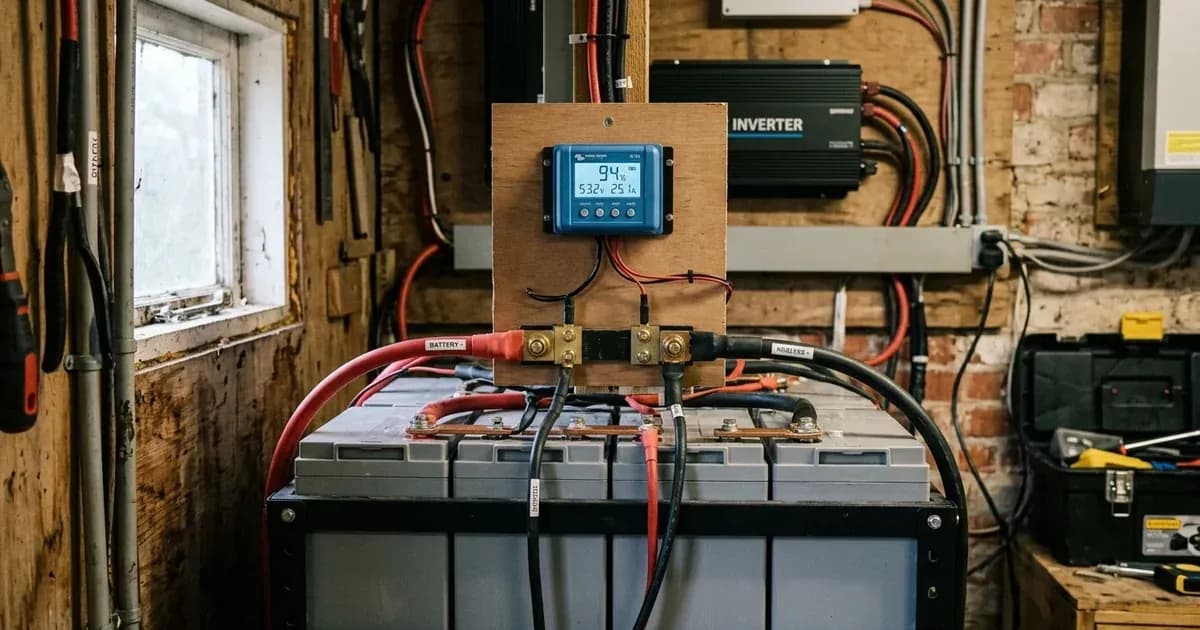
- Coulomb Counting Drift: Lithium BMS units integrate charge current over time (amperes × hours). However, current sensors have noise floors (~0.5 A–0.7 A). If standby inverter electronics draw small currents below this detection threshold, the BMS registers zero consumption while the battery slowly drains, causing the SOC display to freeze.
- The Snap-Correction Jump: When the weakest cell in a pack finally falls toward the under-voltage region — typical LiFePO4 setpoints sit around 2.8 V–3.0 V per cell against an absolute 2.50 V floor, though these are typical figures and your BMS's own datasheet governs — voltage starts moving fast, the running count and the measured reality diverge, and the BMS corrects the displayed SOC in one visible step. Orion BMS's troubleshooting page attributes those jumps to damaged or imbalanced cells, wrong settings and sensor issues. Charge operating temperature window spans 0–55 °C and discharge spans -10–55 °C (charging below 0 °C triggers low-temperature cutoff protection to prevent permanent lithium plating).
Comparison Table: SOC Tracking Mechanisms
Feature / Metric | Flooded Tubular Lead-Acid | LiFePO4 (Voltage Mode) | LiFePO4 (Closed-Loop BMS) |
|---|---|---|---|
Measurement Method | Real-time terminal voltage | Inverter voltage lookup table | BMS shunt coulomb counting |
Behaviour Under Load | Sags with load, rebounds at rest | Sags with load, and the flat curve makes it worse | Counts current, so load alone does not move it |
Flat Curve Effect | Sloping curve, readable once rested | Near-flat plateau: voltage cannot separate SOC levels | Handled by current integration |
Drift Over Time | Resets whenever the bank rests | No memory — re-guesses at every reading | Accumulates until a full charge resets the reference |
True 100% Reference | SG 1.260 @ 25 °C / OCV 12.6 V+ per 12 V block (referenced to 25 °C) | No reliable reference | Full charge to tail current; typical cell over-voltage limits sit near 3.60 V–3.65 V (roughly 57.6–58.4 V on a 16-cell pack), but your BMS datasheet governs |
That table deliberately compares behaviour rather than error bars. We could not find a published accuracy percentage for any of these three methods that we would be willing to print as fact, and an invented accuracy figure would be worth far less to you than knowing which way each method fails.
Step-by-Step SOC Recalibration Procedure
To restore accurate SOC readings across both battery families:
Lithium Battery Recalibration Workflow:
- Charge to the battery's own limit, uninterrupted: with closed-loop comms the battery dictates the charge voltage, so leave it alone. On a manual (voltage-only) setup, use the figure your battery's datasheet prints — not a number from a forum. Two anchors worth knowing: Victron's official Pylontech pairing documentation caps charging at 52.4 V for the 15-cell US series, and cell over-voltage protection on typical LiFePO4 sits near 3.60 V–3.65 V, which is roughly 57.6–58.4 V across a 16-cell pack. Treat those as typical values; your BMS datasheet governs. Note also that on the Voltronic side, Pylontech's own compatibility list states only the Axpert VM III and King support RS485 comms with the battery — every other Axpert type runs on manual voltage settings, so there is no BMS-reported SOC to recalibrate against.
- Let the charge actually finish: hold it until the charger and the BMS agree the pack is full — that is, until the charge current tapers to the tail current your battery's documentation defines, with no load interruption restarting the cycle partway. That uninterrupted finish is the whole point: it is what lets the BMS reset its 100% reference. Two things are worth watching while it sits there:
- Whether the charge current keeps tapering, or stalls at a level that suggests the charger is current-limiting rather than the battery filling.
- Any cell-imbalance alarm the BMS raises near the top of the charge, which is the most useful moment to read it.
- Repeat it on an interval you can name: vendor guidance on recalibration cadence ranges from monthly to quarterly and no industry standard exists, so use whatever your battery's documentation specifies. If it specifies nothing, err toward the more frequent end rather than letting months of shallow partial cycling accumulate uncorrected.
Lead-Acid True SOC Verification:
- Allow a rest period: kill power first and disconnect charging and loads using insulated tools (because an accidental short across battery terminals releases hundreds of amperes) and let the bank sit until the surface charge dissipates. A reading taken while the battery is charging or carrying load tells you nothing about its state. Wear eye protection against corrosive sulfuric acid splashes whenever servicing cells, and top up with distilled water only, never acid. Do not read specific gravity straight after topping up with distilled water either — run a cycle first so the electrolyte mixes properly.
- Check Open-Circuit Voltage and Specific Gravity against Osaka's published ladder (per 12 V block, referenced to 25 °C):
- 100% SOC: OCV 12.6 V+ per 12 V block / SG = 1.260 (referenced to 25 °C).
- 75% SOC: OCV = 12.35 V / SG = 1.220 (referenced to 25 °C).
- 50% SOC: OCV = 12.20 V / SG = 1.190 (referenced to 25 °C).
- 25% SOC: OCV = 12.00 V / SG = 1.150 (referenced to 25 °C).
- 0% Discharged: OCV = 11.80 V / SG = 1.120 (referenced to 25 °C).
- Correct for temperature before you trust a borderline reading: hydrometer readings want roughly 4 points of correction per 6 °C away from 27 °C. Wear eye protection when testing specific gravity to protect against corrosive sulfuric acid. Note too that the Osaka data sheet prints its specific-gravity reference temperature as 25 °C in one place and 20 °C in another, so check which reference your hydrometer assumes rather than treating a hair's-breadth difference as a verdict. Lead-acid charging setpoints (57.6–58.8 V at 48 V; Axpert flooded 58.4 V; Deye Wet 59.0 V) are referenced to 25 °C and require -3 to -5 mV/cell/°C temperature compensation for hot ambient installations (equalization at 58.4 V must be conducted in an actively ventilated space away from sparks and flames because equalization deliberately drives cells into the explosive hydrogen gassing region).
For overall capacity sizing, consult our guide on how many kWh of battery storage you need. If your battery shows 100% capacity but the inverter refuses to supply load power, consult our guide on solar battery not discharging. To decode underlying BMS alarm states, see our BMS error codes and protection states glossary.
Safety: Working with Inaccurate Battery Systems
Observe these essential safety guidelines during SOC diagnosis:
- Deep Discharge Danger: an SOC gauge you cannot trust invites over-discharge. On lead-acid, running a bank flat and leaving it parked there feeds sulfation, and Battery University's distinction matters here: early, soft sulfation can still be reversed by a proper full charge or controlled equalization in an actively ventilated space away from sparks and flames (because equalization deliberately drives cells into the explosive hydrogen gassing region), while hard crystallised sulfation is not recoverable. Time, not heroics, decides which one you are dealing with. On lithium, the system will cut off — either at the inverter's low-DC cutoff (Axpert default 42.0 V on a 48 V basis, adjustable 42–48 V) or at the BMS's own cell-level under-voltage protection — protection working as designed, not a fault to be worked around.
- Thermal Safety: during a long calibration charge, put a hand on the battery from time to time. A case too hot to hold comfortably — installers and forum users here put that line around 50 °C+, a community-reported threshold rather than a published manufacturer spec — means come off charge immediately and find out why before continuing. Flooded cells gas hydrogen throughout charging (equalization deliberately enters the gassing region near 2.4 V per cell), so the room needs real ventilation and no sparks near the vents. Wear eye protection against corrosive sulfuric acid splashes; add distilled water only, never acid.
- Swollen Battery Hazard: a swollen battery of either chemistry represents dangerous internal pressure and a severe fire hazard. Stop charging immediately, isolate the pack, and replace it. On lithium packs, never attempt to puncture or relieve pressure on a swollen module.
- Terminal and Electrical Safety: kill power first, disconnect the negative terminal first, and use insulated tools whenever tightening or inspecting connections, because a metal tool dropped across a 48 V bank shorts hundreds of amperes.
- Before you open anything: inverter capacitors can hold a lethal charge for up to 5 min after shutdown, and PV conductors stay live in daylight regardless of what the inverter is doing.
When to call a technician instead
Contact a certified solar technician under the following conditions:
- A lithium pack that keeps snap-correcting hard — reading healthy one minute and near-empty the next — through several complete, uninterrupted recalibration charges. That pattern points at a collapsed cell rather than a lazy counter.
- Specific-gravity readings (measured with a hydrometer wearing eye protection against corrosive sulfuric acid) that spread across cells in the same block and do not close up after a full charge (and, where the manufacturer permits one, an equalization charge in an actively ventilated area away from sparks and flames, because equalization deliberately drives cells into the explosive hydrogen gassing region). A spread that charging no longer restores is the classic single-dead-cell signature. No Pakistani brand publishes a pass/fail spread figure, so read the trend across repeated checks rather than looking for a threshold number.
- The BMS reports a communication fault or stops reporting individual cell voltages at all — on a Deye hybrid that surfaces as F58, and installer references report Growatt's equivalent as Warning 20 (Solis reports CAN_Comm-Fail / BAT_Comm-Fail / No Battery).
- Any battery module showing physical swelling, cracked casings, or leaking electrolyte.
For professional maintenance standards, consult our guide on when to call a solar technician and our guide on lithium battery inverter compatibility errors.
Figures as of August 2026.
Still showing the fault? Book a technician
If the steps above did not clear it, tell us the inverter or battery and the exact code. We pass it to a technician who covers your city; visit charges are quoted before they come.
How this pays for the site: the technician or verifier pays SolarNevs a fixed introduction fee. Nobody pays to be recommended, and you are free to use our free guides instead.
Frequently asked questions
Why is my lithium battery State of Charge percentage stuck at one value?
Lithium BMS units track capacity using current sensors (coulomb counting). When low background currents (below 0.5 A–0.7 A noise floors) flow continuously, the sensor registers zero current while the battery drains, causing the displayed SOC percentage to freeze until a voltage limit is reached.
Why does my battery percentage suddenly jump down from a healthy reading to almost empty?
LiFePO4 cells hold a flat plateau near their 3.2 V nominal figure for most of the discharge, so the displayed percentage rests on counting rather than on voltage. When a weak or imbalanced cell finally falls toward the under-voltage region — typical LiFePO4 setpoints sit around 2.8 V–3.0 V per cell against an absolute 2.50 V floor, though your own BMS datasheet governs — voltage moves fast, the count and the measurement disagree, and the BMS snaps the display down to match. Orion BMS lists damaged or imbalanced cells, wrong settings, and sensor problems as the usual causes.
Why does my inverter show 100% battery, but the power shuts off minutes later?
A non-communicating inverter has no capacity meter on a lead-acid bank — it infers the percentage from terminal voltage, which installers commonly describe as a voltage guess rather than a gauge (community framing, not a manufacturer specification). A battery still carrying surface charge from a short utility charge, or one whose plates are sulfated, reads high while holding very little usable capacity, so it collapses as soon as load arrives. The honest check is a rested open-circuit voltage or specific-gravity reading per 12 V block: 12.6 V+ or better (SG 1.260 at 25 °C reference) is a full 12 V block, 11.80 V (SG 1.120) is flat. Wear eye protection whenever drawing electrolyte into a hydrometer because drawing electrolyte out exposes you to corrosive sulfuric acid, and add distilled water only, never acid.
How do I recalibrate an inaccurate lithium battery SOC meter?
Give it one uninterrupted full charge — no load interruptions restarting the cycle — held until the charge current tapers to the tail current your battery's own documentation defines as full. That uninterrupted finish is what lets the BMS reset its 100% reference. Vendor advice on how often to repeat it ranges from monthly to quarterly with no industry standard, so follow the interval your battery's documentation gives.
Why do the battery BMS and solar inverter display different SOC percentages?
The battery BMS counts current through its own internal shunt, whereas a non-communicating inverter estimates SOC from terminal voltage. Two estimators drift apart: one vendor write-up (Eneronix — a single source, so treat the figure as illustrative) documents a pair diverging from 2% to 12% over 8 weeks without a recalibration charge. Closed-loop CAN or RS485 comms remove the second guess by letting the battery report its own numbers to the inverter.
References
- Osaka Tubular Technical Data Sheet — accessed 23 August 2026
- Orion BMS SOC Jump Troubleshooting Guide — accessed 23 August 2026
- Pylontech US5000 Operation Manual PDF — accessed 23 August 2026
- Axpert V PF1 User Manual — accessed 23 August 2026
- Growatt SPF 5000 ES User Manual — accessed 23 August 2026
- Victron Energy Pylontech Battery Compatibility Manual — accessed 23 August 2026
- Eneronix SOC Drift in Lithium Battery Systems — accessed 23 August 2026
Related guides
More from inverter errors & fixes.