Lithium Communication Wiring: CAN vs RS485 Pinouts for Inverters
Updated 6 September 2026 · By SolarNevs Research Desk, Dealer surveys + verified sources · 7 sources · Method ↗
Key Takeaways
- CAN and RS485 are electrically distinct physical layers; connecting a CAN battery port to an RS485 inverter port will not function (CAN↔CAN or RS485↔RS485 only; CAN to RS485 will not work without hardware protocol conversion).
- The dominant 48V LiFePO4 rack standard (Pylontech pattern) assigns Pin 4 to CANH, Pin 5 to CANL, and Pin 2 to GND (pins 1, 3, 6–8 unused).
- CAN networks require a 120Ω terminator at each bus end; missing and duplicate terminators both cause communication faults (such as Deye F58 or Growatt Warning 20).
- Standard plain LAN cables frequently cause communication faults; manufacturer-supplied or custom-pinned cables matching CAN-H/CAN-L/RS485 lines exactly are required.
- In multi-battery racks, Battery 1 must be addressed as master (address 0/1 via DIP switch, display, or software), with slaves linked via Link-In/Link-Out ports.
Quick Answer: How to wire CAN and RS485 cables for lithium inverters
To establish closed-loop communication between a 48V LiFePO4 battery BMS and a hybrid inverter (such as Deye, Solis, Growatt, Victron, or Axpert), you must match physical protocols and pinouts exactly.
For CAN communication, connect CAN-H to CAN-H and CAN-L to CAN-L. On the common Pylontech pattern that means battery Pin 4 → inverter Pin 4 and battery Pin 5 → inverter Pin 5. BYD HV batteries instead carry CAN-H on Pin 1 and CAN-L on Pin 2, so they need a cross-pinned cable to the inverter's pins 4/5 — a straight cable will not work. For RS485 communication, match differential lines according to the manufacturer manual (for example, Growatt SPF communicates via its RS485 port using Pylontech profile 2 in Program 36).
Ensure that unused pins are left unconnected to prevent electrical cross-talk, designate Battery 1 as Master (address 0/1), and verify that 120Ω bus termination is enabled at both physical ends of the communication bus.
Master Pinout Reference Table for Lithium Solar Inverters
The table below compiles verified RJ45 pinout assignments across major lithium storage packs and inverter platforms in Pakistan:
Device / Interface | Port Type | Pin 1 | Pin 2 | Pin 3 | Pin 4 | Pin 5 | Pin 6 | Pin 7 | Pin 8 |
|---|---|---|---|---|---|---|---|---|---|
Pylontech CAN (battery side) | CAN Port | Null | GND | Null | CANH | CANL | Null | Null | Null |
Solis S5 / S6 Hybrid Inverters | Battery Port | Null | Null | Null | CAN-H (blue) | CAN-L (blue/white) | Null | Null | Null |
BYD HV Battery (CAN side) | CAN Port | CAN-H | CAN-L | Null | Null | Null | Null | Null | Null |
Deye SUN-…SG03LP1 Hybrids | BMS Port | Null | Null | Null | CAN-H (std) | CAN-L (std) | Null | Null | Null |
Pinout assignments verified against manufacturer documentation (Solis, BYD via Solis doc) or double-sourced installer references (Pylontech, Deye). For Solis, pin assignments apply across models S6-EH3P(5-10)K-H-EU, RHI-3P HVES-5G, RHI-48ES-5G, S5-EH1P-L, and S6-EA1P-L. Note that for Pylontech RS485 ports, install-guide recommendations suggest pins 7/8 (pin 7 RS485-A side per 568B wiring), but this is single-sourced and requires verification against your specific model manual before connecting pin letters.
Inverter Pairing and Protocol Configuration Reference
Establishing BMS closed-loop control requires configuring inverter parameters to match battery protocol specifications:
Inverter Family | Battery Setting | Communication Interface | Protocol / Program Settings | Critical Manufacturer Caveats |
|---|---|---|---|---|
Axpert VM III / King | Program 05: Lithium presets (PYL/WEC/SOL/LIb) | RS485 BMS Port | Program 29 default 42.0V (range 42-48V); Program 02 up to 80A (utility 60A) | RS485 BMS comms supported on VM III and King only per Pylontech list; other Axpert types require manual voltage settings |
Growatt SPF 5000 ES | Program 05: LI (Lithium) | RS485 Port (or CAN) | Program 36: SCI/RS485 options L01-L15 (Pylontech = profile 2) or CAN options L51-L65 (profile 52) | Only one comm type at a time; max charge current locked by BMS; Pylontech pairing REQUIRES DoD ≤80% |
Deye SUN-…SG03LP1 | Lithium Mode | CAN Port (Pins 4/5) | BMS protocol code per Approved Battery document | Straight-through Ethernet cable works with matching batteries; F58 indicates comms fault; avoid generic codes 00/12 without checking table |
Solis S5 / S6 LV Hybrids | Li-BMS mode | CAN Port (Pins 4/5) | CAN-H pin 4 / CAN-L pin 5 | Official Pylontech US-series clearance; comms errors reported as CAN_Comm-Fail / BAT_Comm-Fail / No Battery |
Victron (with GX device) | Pylontech profile via GX | VE.Can Port | BMS-managed charge capped at 52.4V (for 15-cell US series) | Requires Victron type-A VE.Can-to-CAN-bus BMS cable; Pylontech-supplied cable will NOT work (battery invisible, shuts itself off) |
Step-by-Step Wiring and Diagnostic Procedures
1. Protocol Architecture: CAN Bus vs RS485
Solar battery communication relies on two distinct physical and data layers:
- Controller Area Network (CAN Bus): High-speed, multi-master, message-based protocol using differential signaling between CAN-H and CAN-L. It is the dominant standard for modern hybrid inverters (Deye, Solis, Victron).
- RS485: Differential serial bus operating under Master/Slave polling. Commonly used for internal battery daisy-chaining (Link-In/Link-Out) and off-grid inverter platforms like Axpert VM III and Growatt SPF 5000 ES.
- Incompatibility Rule: CAN↔CAN or RS485↔RS485 only; CAN to RS485 will not work without an active protocol bridge.
- Protocol Layer Incompatibility: Even when physical wiring matches, software protocols differ; Pylontech, PACE, Growatt, Victron, and LuxPower protocols are mutually incompatible (matching connector ≠ compatibility). Because no universal per-model protocol-code matrix is published for the Pakistan market, installers must demand the exact BMS protocol code in writing from the equipment distributor.
2. Cable Construction: Straight-Through vs Dedicated BMS Leads
A frequent installation pitfall in Pakistan is using generic pre-molded network cables between battery and inverter:
- Why Generic LAN Cables Fail: Inverters often allocate RS485 lines and CAN lines within different pins of the same RJ45 socket. A standard plain LAN cable can cross-connect incompatible circuits or introduce electrical interference onto differential pairs.
- Pinout Discrepancy Example: On Solis inverters, CAN-H sits on Pin 4 and CAN-L on Pin 5. On BYD HV batteries, CAN-H sits on Pin 1 and CAN-L on Pin 2. Inserting a standard straight cable between Solis and BYD results in total communication failure because differential pairs are mismatched.
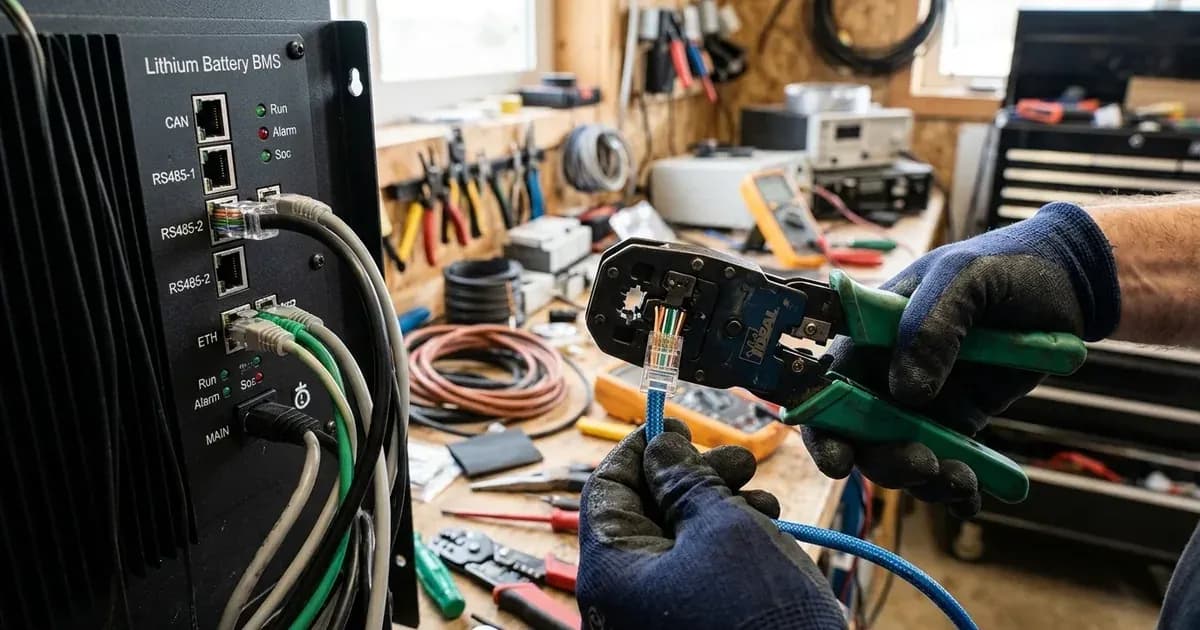
- Dedicated Cable Assembly: Use manufacturer-supplied cables or crimp custom patch leads where conductors connect exclusively to designated pins (e.g. Pin 4 to Pin 4 for CAN-H, Pin 5 to Pin 5 for CAN-L, and Pin 2 to Pin 2 for GND), keeping unused pins isolated. Always inspect connectors for bent pins prior to insertion.
3. CAN Bus 120 Ohm Termination Rules
High-speed CAN signals propagate along communication wiring as transmission line waves:
- Signal Reflection Faults: When high-frequency differential signals hit an unterminated cable end, signal energy reflects back, creating destructive interference that corrupts packet checksums and triggers communication timeouts.
- Termination Requirement: A 120Ω terminator must be present at each electrical end of the bus.
- Dual Failure Modes: Crucially, missing and duplicate terminators both cause faults. If both ends are unterminated, signal reflection corrupts data; if extra terminators are connected in parallel, bus impedance drops excessively, overloading transceivers and triggering fault alarms (e.g. Deye F58 or Growatt Warning 20).
4. Multi-Module Daisy-Chain Architecture (Link-In / Link-Out)
When connecting multiple 48V LiFePO4 rack modules in parallel (modules range from 2.4 to 5.12 kWh, such as US3000C 3.55kWh or US5000 4.8kWh, stackable to ~16 modules per string):
- Internal Daisy-Chain: Connect standard RJ45 patch leads from Link-Out of the Master battery to Link-In of Slave 1, Link-Out of Slave 1 to Link-In of Slave 2, continuing sequentially through all packs.
- Master Addressing: Designate Battery 1 as Master (address 0/1 via DIP switch, display, or software). Slaves report their internal cell data across the daisy chain, and the Master aggregates telemetry to present the complete bank to the solar inverter. Wrong addressing results in no communication ("BMS lost").
- Inverter Uplink: Connect the dedicated CAN or RS485 Inverter BMS port of the Master module directly to the solar inverter communication socket.
5. Diagnostic Verification Procedures
Before powering up a newly wired communication interface, verify physical and electrical parameters:
- Pin Continuity Verification: Use a digital multimeter in continuity mode to confirm that Pin 4 connects exclusively to Pin 4, Pin 5 to Pin 5, and Pin 2 to Pin 2, confirming no short circuits between pins or to the connector shell.
- Bus Termination Resistance Measurement: With the inverter and battery completely powered off, measure resistance between CAN-H (Pin 4) and CAN-L (Pin 5) at a connected bus node, with both bus-end devices attached: approximately 60Ω means both 120Ω terminators are present (two in parallel); approximately 120Ω means only one; open/very high means none.
- Port and Address Confirmation: Confirm that the cable is plugged into the Master Inverter BMS port (not an internal Link port) and that Battery 1 master address (0/1) is active.
Review comprehensive protocol fault handling in our guide on lithium battery inverter compatibility errors and decode protection flags in BMS error codes and protection glossary. For percentage calibration issues, see battery SOC stuck or jumping fixes and learn fundamental BMS protection mechanisms in BMS functions and battery protection.
Safety: Inverter Communication and High-Voltage DC Precautions
Observe these mandatory electrical safety rules when modifying communication cabling:
- Capacitor Discharge Duration: Inverter DC capacitors hold lethal charge up to 5 minutes after shutdown; solar PV conductors remain live in daylight. Always wait at least 5 minutes after opening DC isolators before servicing connections.
- Isolate High-Voltage DC: Always open DC battery circuit breakers and solar array disconnects before plugging, unplugging, or re-pinning communication cables.
- Conduit Separation: Never route RJ45 communication cables parallel to high-current DC power cables in the same trunking or conduit. Inductive switching spikes from hybrid inverters corrupt differential communications.
- Physical Lifting Safety: 48V LiFePO4 rack modules are heavy (e.g. Pylontech US5000 weighs 39.7kg); always use a two-person lift when racking modules.
When to call a technician instead
Contact a certified solar professional under the following circumstances:
- The inverter consistently reports communication failure (Deye F58, Growatt Warning 20, Solis CAN_Comm-Fail / BAT_Comm-Fail / No Battery, or Inverex/Knox BMS lost) despite verifying custom Pin 4/5 cabling and protocol selection.
- Internal BMS communication transceivers fail to establish bus activity or show physical connector damage.
- Parallel battery modules fail to synchronize across Link-In / Link-Out daisy chains.
For professional escalation standards, consult our guide on when to call a solar technician.
Figures as of August 2026.
Still showing the fault? Book a technician
If the steps above did not clear it, tell us the inverter or battery and the exact code. We pass it to a technician who covers your city; visit charges are quoted before they come.
How this pays for the site: the technician or verifier pays SolarNevs a fixed introduction fee. Nobody pays to be recommended, and you are free to use our free guides instead.
Frequently asked questions
Can I connect an inverter RS485 port to a battery CAN port using an adapter?
No. CAN bus and RS485 are fundamentally incompatible physical and electrical protocols; CAN to RS485 will not work without active hardware protocol translation. CAN uses differential signaling with multi-master arbitration, while RS485 operates under Master/Slave polling. Connecting across protocols causes permanent communication failure.
What is the standard RJ45 pinout for Pylontech CAN communication?
On Pylontech battery modules, the CAN interface uses Pin 4 for CANH (High), Pin 5 for CANL (Low), and Pin 2 for GND, with pins 1, 3, 6, 7, and 8 remaining unused. Note that protocol layers are brand-specific, so matching physical connector pinouts alone does not guarantee protocol compatibility.
Why is a 120 ohm termination resistor required on CAN bus lines?
CAN bus operates as a high-speed transmission line requiring a 120Ω terminator at each bus end. Without proper termination, signal reflections corrupt data packets, causing BMS communication faults such as Deye F58 or Growatt Warning 20. Crucially, missing and duplicate terminators both cause faults.
How do I make a custom BMS communication cable for a Growatt SPF inverter?
For a Growatt SPF 5000 ES paired with Pylontech batteries, communication is documented over the RS485 port using profile 2 in Program 36 with battery type set to LI in Program 05, where max charge current is locked by the BMS and DoD must be ≤80%. An installer-reported CAN route with profile 52 also exists. Pins must match CAN-H/CAN-L or RS485-A/B lines exactly.
What is the difference between Link-In/Link-Out and Inverter BMS ports on a battery rack?
Link-In and Link-Out ports are internal daisy-chain ports connecting parallel slave packs to the master module. Only Battery 1 is designated as master (address 0/1 via DIP switch, display, or software) and connects its CAN or RS485 BMS port to the solar inverter.
References
- Pylontech Inverter Compatibility List Ver 2.40 — accessed 23 August 2026
- Pylontech US5000 Operation Manual PDF — accessed 23 August 2026
- Pylontech US5000 Technical Datasheet — accessed 23 August 2026
- Growatt SPF 5000 ES User Manual via ManualsLib — accessed 23 August 2026
- Axpert VM III User Manual — accessed 23 August 2026
- Solis Inverters Communication Ports for Battery Connection — accessed 23 August 2026
- Victron Energy Pylontech Battery Compatibility Guide — accessed 23 August 2026
Related guides
More from inverter errors & fixes.