Pylontech US5000 and UP5000 Rack Battery Setup Guide
Updated 7 September 2026 · By SolarNevs Research Desk, Dealer surveys + verified sources · 2 sources · Method ↗
Key Takeaways
- Pylontech US5000 and UP5000 modules operate at a "48V" nominal voltage with a "4.8KWh" capacity.
- A Victron GX device (e.g., Cerbo GX) is essential for BMS communication and system control.
- Correct CAN-bus cabling, termination, and DIP switch settings ('000') are critical for detection and operation.
- The battery's internal BMS will restrict charge current in cold weather, potentially reducing PV output.
- Specific DC busbar sizing and rack mounting details are not provided in manufacturer documentation, requiring careful planning by the installer.
Setting up Pylontech US5000 and UP5000 batteries with a Victron system
The Pylontech US5000 and UP5000 are 48V, 4.8kWh lithium iron phosphate (LFP) rack-mounted batteries designed for solar energy storage systems. Proper installation and configuration, particularly with Victron Energy systems, rely on establishing robust communication between the battery's internal Battery Management System (BMS) and the Victron GX device. This guide outlines the necessary steps and settings to integrate these Pylontech models into a functional energy storage setup.
Understanding BMS Communication and System Integration
The core of integrating Pylontech US5000 and UP5000 batteries with a Victron system is the CAN-bus communication. The Pylontech BMS actively manages the battery's state, including charge and discharge limits, state of charge (SOC), and error conditions. A "GX-device is required, eg Cerbo GX or Venus GX (VGX)" to interface with the Pylontech BMS. This device "communicates the keep-alive signal, charge and discharge limits, error codes and state of charge (SOC %) between the batteries and the system." Without this communication, the Victron inverter/charger or MPPT will not receive critical operational data, leading to system errors or improper battery management.
The Pylontech US5000 and UP5000 models feature an LFP chemistry, which offers enhanced safety due to a more stable internal molecular structure. This allows for an "increase in the combustion temperature of 600°C compared to 300°C relative to NMC and LCO."
Pylontech US5000 and UP5000 Module Specifications
Parameter | Pylontech UP-5000 Specification | Pylontech US5000 & UP5000 Specification | Technical Reference |
|---|---|---|---|
Nominal Voltage | "48v" | "48V" | buysolar.pk / Victron Energy |
Ampere-hour Capacity | "100AH" | N/A | buysolar.pk |
Module Capacity | "4.8KWh" | "4.8 kwh" | buysolar.pk / Victron Energy |
Max Power Output (single module) | "Provides up to 5KW with a single 4.8 KWh module" | N/A | buysolar.pk |
Depth of Discharge (DoD) | "90% DoD" | N/A | buysolar.pk |
Cycle Life | "more than 6000 cycles with 90% DoD" | N/A | buysolar.pk |
Design Life | "The expected design life is 15+ years" | N/A | buysolar.pk |
Operating Temperature Range | "Working temperatures of between 0°C to 50°C" | N/A | buysolar.pk |
Pylontech US5000 and UP5000 Setup Procedure
Follow these steps to correctly connect and configure your Pylontech US5000 or UP5000 batteries with a Victron GX device:
- Firmware Check: Ensure your GX device is running "minimum required firmware version for the [[venus-os-start|GX Device (e.g. Cerbo GX ]] is v2.42."
- DIP Switch Configuration: Set the address DIP-switches on the master Pylontech battery to "000". The "GX device will not detect the battery if you use any other setting."
- CAN-bus Cable Connection: Use the "Victron //VE.Can to CAN-bus BMS type A Cable//, part number ASS030710018".
- "Plug the communication cable with the side which is labeled Battery BMS into the Pylontech CAN port of the master battery."
- "Plug the side labeled Victron VE.Can into the [[venus-os-start|GX device]]."
- GX Device CAN Port Configuration:
- If your GX device has a dedicated BMS-Can port, use it.
- If your GX device only has VE.Can ports, "you will need to change the VE.Can port profile to CAN-bus BMS (500 kbit/s) for the battery."
- CAN-bus Termination: "Then, plug a [[https://www.victronenergy.com/accessories/ve-can-rj45-terminator|VE.Can terminator]] in the other VE.Can socket on the [[venus-os-start|GX device]]."
- Parallel Battery Connection: If using multiple battery modules, connect them using the RJ-45 cables supplied by Pylontech via the link ports. The "battery with the empty link port 0 is the master battery." Note that "Other models can connect up to 8 battery modules (see Pylontech data sheets), in those models when using more than 8 parallel units, some limitations, additional configuration or equipment (e.g. Pylontech LV-Hub) may apply."
Victron System Settings for Pylontech US5000/UP5000
The following settings are recommended for Victron Energy components when paired with Pylontech US5000 or UP5000 batteries. These settings ensure proper communication and battery management by the Pylontech BMS.
System/Component | Setting Name | Value | Technical Reference |
|---|---|---|---|
Victron GX Device | DVCC | "ON" | Victron Energy |
Victron GX Device | Shared Voltage Sense | "OFF" | Victron Energy |
Victron GX Device | Shared Temperature Sense | "OFF" | Victron Energy |
Victron VEConfigure Charger | Battery type | "Lithium" | Victron Energy |
Victron VEConfigure Charger | Charge curve | "Fixed" | Victron Energy |
Victron VEConfigure Charger | Absorption voltage | "52.0 V" | Victron Energy |
Victron VEConfigure Charger | Float voltage | "51.0 V" | Victron Energy |
Victron VEConfigure Charger | Absorption time | "1 Hr" | Victron Energy |
Victron VEConfigure Inverter | DC input low shut-down | "44V" | Victron Energy |
Victron VEConfigure Inverter | DC input low restart | "48V" | Victron Energy |
Victron VEConfigure Inverter | DC input low pre-alarm | "48V" | Victron Energy |
Victron ESS Assistant | Battery System Selection | "externally managed Lithium battery option" | Victron Energy |
Victron ESS Assistant | Sustain voltage | "48V" | Victron Energy |
Victron ESS Assistant | Dynamic cut-off values | "set all values to 46V." | Victron Energy |
Victron ESS Assistant | Restart offset | "1.2V (Default)" | Victron Energy |
Victron VE.Direct MPPT | Battery voltage | "48V" | Victron Energy |
Victron VE.Direct MPPT | Absorption voltage | "52V" | Victron Energy |
These absorption and float setpoints are documented at a 25°C reference. The battery's own charging temperature range is 0-50°C, so in a hot rooftop enclosure or direct sun, confirm the pack is within range and not derating before assuming the setpoints above still apply unmodified.
Common Faults and Resolutions
Code / Status / Symptom | Meaning | Fix Direction | Technical Reference |
|---|---|---|---|
"Internal Error" (battery status) | "some of the slave batteries are offline(which is due to these modules have been discharged to an extremely low SOC or being in idle mode for more than 72hrs)" | "once the system is available for a charging activity such an error will be automatically eliminated." | Victron Energy |
"High cell voltage" (warning or alarm) | "not unusual on new batteries that are not yet balanced." | "To help the batteries balance quickly, keep the batteries fully charged until the errors go away." | Victron Energy |
"error #67: no BMS" (MPPT LED) | MPPT not receiving BMS data from GX device. | "try disconnecting the [[venus-os-start | GX device]] from the MPPT. After a time-out, the MPPT will stop charging and flash an error code on its LEDs." | Victron Energy |
Inverter/Charger or GX device does not switch on, system is hard off. | "battery becomes completely discharged the battery will further protect itself by not just sending the 0A discharge limit, but also disconnecting DC voltage from the battery terminals (via internal MOSFETS)." | N/A | Victron Energy |
System not charging at rated capacity, or PV is shutting down. | "Pylontech's BMS will restrict the Charge Current Limit of the battery in cold weather." | N/A | Victron Energy |
Charge current often changes between 0A and 25A. | "caused by cell balancing inside the battery. This happens with new batteries and after a deep discharge." | N/A | Victron Energy |
Battery won't charge to 100%. | "Because we cap the battery voltage at 52.4V, the state of charge will sometimes rise very slowly once it reaches the mid-90s." | N/A | Victron Energy |
Installation safety and switchgear requirements
Working with high-voltage and high-current battery systems requires strict adherence to safety protocols. Pylontech US5000 and UP5000 batteries operate at a nominal "48V" and can deliver significant current.
- Isolation: Before making any DC connections, ensure all power sources are isolated. This includes turning off PV array isolators, AC breakers to the inverter/charger, and any battery breakers.
- Power Down: Always power down the entire system, including the inverter/charger and GX device, before connecting or disconnecting battery terminals or communication cables.
- Personal Protective Equipment (PPE): Wear appropriate PPE, including insulated gloves, eye protection, and non-conductive footwear, when working with battery terminals.
- Insulated Tools: Use insulated tools to prevent accidental short circuits when tightening or disconnecting battery terminals. A spanner across a 48V battery bank can short hundreds of amps, leading to severe burns or equipment damage.
- DC Breakers: Install appropriately rated DC circuit breakers or fuses between the battery bank and the inverter/charger. The Pylontech BMS provides internal protection, but external overcurrent protection is mandatory for system safety. The battery has "102A for 15 seconds, 200A for 0.1 seconds and 400A short circuit current" over-charge and over-discharge current limits.
- Earthing: Ensure the battery rack and inverter/charger chassis are properly earthed according to local electrical codes.
- Voltage Protection: The battery has internal protection that activates if the voltage drops to "44.5V or less" or if the charging voltage rises "above 54V". The "Discharge Current Limit set to 0A at 47V" will cause the inverter to turn off. These thresholds are the manufacturer's 25°C-reference figures; in a hot rooftop enclosure, confirm the pack is within its 0-50°C charging range before assuming they apply unmodified.
- Temperature: The "Working discharge temperature range is from -10 to 50 degrees celsius," and the "Charging temperature range is from 0 to 50 degrees celsius." Operating outside these ranges can affect performance and safety.
- Authorised Service: Opening the battery enclosure, replacing internal components, or re-pinning connectors should only be performed by authorised service personnel.
What the published sources do not tell you
While the provided documentation covers essential setup and operational parameters for Pylontech US5000 and UP5000 batteries, several practical details are not explicitly addressed:
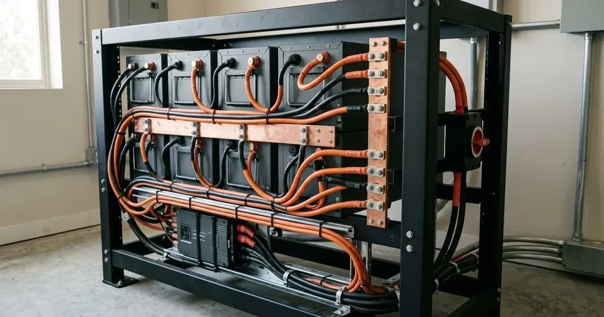
- DC Busbar Sizing: Specific recommendations for DC busbar sizing for multi-module Pylontech installations are not provided. Installers must calculate appropriate busbar and cable sizes based on the total current draw of the system.
- Ground Lug Wiring: Detailed instructions or recommendations for ground lug wiring on the Pylontech US5000 or UP5000 modules are not available, requiring reliance on general electrical practice.
- Rack Mounting Installation: The documentation does not include detailed steps or specifications for physically mounting the batteries into a server rack, which is a common installation method for these models.
- Continuous Charge/Discharge Current: While the UP5000 is rated at "100AH", the continuous charge/discharge current (C-rate) for the US5000/UP5000 modules is not explicitly stated. This information is crucial for system design and sizing.
- Peak Power Output for US5000: Only the UP5000 is stated to "Provides up to 5KW with a single 4.8 KWh module"; a similar peak power figure for the US5000 model is not provided in the available sources.
- US5000 Feature Confirmation: Features like "Advanced BMS that allows you to report alarms in real-time" and "Modular design gives end-customers the ability to choose capacity" are listed for the UP5000 on some retail sites but are not explicitly confirmed for the US5000 in the provided technical sources.
- "4.5000 life-span warranty" Clarification: A "4.5000 life-span warranty" mentioned on a retail site appears to be a typo, and its exact meaning (e.g., 4500 cycles or 4.5 years) is not clarified in technical documentation.
These omissions mean installers may need to consult general electrical standards, best practices for battery installations, or seek clarification directly from Pylontech for specific design considerations.
Still showing the fault? Book a technician
If the steps above did not clear it, tell us the inverter or battery and the exact code. We pass it to a technician who covers your city; visit charges are quoted before they come.
How this pays for the site: the technician or verifier pays SolarNevs a fixed introduction fee. Nobody pays to be recommended, and you are free to use our free guides instead.
Frequently asked questions
What is the nominal voltage and capacity of a Pylontech US5000 or UP5000 module?
A Pylontech UP-5000 module has a '48v' nominal voltage and '100AH' capacity, equating to '4.8KWh'. The Pylontech US5000 also has a '48V' nominal voltage and '4.8 kwh' module capacity.
Is a Victron GX device required for Pylontech US5000/UP5000 batteries?
Yes, a 'GX-device is required, eg Cerbo GX or Venus GX (VGX)' for BMS communication. It 'communicates the keep-alive signal, charge and discharge limits, error codes and state of charge (SOC %) between the batteries and the system'.
What communication cable is needed to connect Pylontech US5000/UP5000 to a Victron GX device?
The 'Victron //VE.Can to CAN-bus BMS type A Cable//, part number ASS030710018' is used. One side, labelled 'Battery BMS', plugs into the Pylontech master battery's CAN port, and the 'side labeled Victron VE.Can' plugs into the GX device.
How should the DIP switches be set on Pylontech US5000/UP5000 batteries for Victron systems?
The address DIP-switches must be set to '000' for correct operation. The 'GX device will not detect the battery if you use any other setting'.
Why might a Pylontech US5000 or UP5000 battery not charge to 100%?
This can occur 'Because we cap the battery voltage at 52.4V'. The 'state of charge will sometimes rise very slowly once it reaches the mid-90s'.
References
- buysolar.pk Pylontech UP-5000 Product Page — accessed 29 August 2026
- Victron Energy Pylontech Compatibility Guide — accessed 29 August 2026
Related guides
More from inverter errors & fixes.