Ziewnic Battery Not Charging From Solar: Troubleshooting Guide
Updated 7 September 2026 · By SolarNevs Research Desk, Dealer surveys + verified sources · 7 sources · Method ↗
Key Takeaways
- Incorrect inverter configuration, particularly Program 16 (Charger source priority), is the primary cause when a Ziewnic inverter fails to charge its battery bank from solar or grid.
- Verify that your solar array operating voltage matches your inverter model's MPPT operating range (55-430 VDC for Diamond II 6G, 90~450 VDC for Diamond 5G, 120~500VDC for Roux, or 125 - 430 VDC / 200 - 650 VDC for Lenox).
- During battery equalization on flooded lead-acid batteries (Program 30/31), cells are driven into the explosive hydrogen gassing region and require positive cross-ventilation away from sparks and flames. Never equalize sealed lithium or AGM/gel batteries.
- Always kill power first and use insulated tools before inspecting or tightening battery terminals, because a metal spanner across battery terminals shorts hundreds of amps.
- If the battery voltage collapses below 1.91 V per cell (<22.9 V on 24V or <45.8 V on 48V), the inverter shuts down automatically during startup; below 1.4 V per cell (<16.8 V on 24V or <33.6 V on 48V), the screen remains blank.
Why is my Ziewnic inverter battery not charging from solar or grid?
If your Ziewnic inverter is not charging its battery bank, the most common causes are misconfigured charger source priority settings (Program 16), charging current limits (Program 02 / 11), or solar PV input voltage falling outside the inverter's active MPPT tracking window. Diagnosing the issue requires checking the LCD status screens, verifying solar string DC voltage, inspecting grid input thresholds, and confirming battery bank health.
Diagnosis
Steps 1-2 and all Program numbers below apply to the Voltronic-platform lines (Axpert Ultra, Axpert Twin Premium +, Diamond, Max); identify your series from the model label first.
- Check Inverter LCD for Active Fault and Warning Codes:
- Observation: Look for active 2-digit fault codes or warning codes on the inverter LCD display.
- Meaning: Fault 03 indicates battery voltage is too high, while Fault 04 indicates battery voltage is too low. Warning 03 (Battery is over-charged) and Warning 04 (Low battery) sound an audible beep once every second. Warning 15 indicates PV energy is low, while Fault 59 indicates PV voltage is beyond the acceptable range. For comprehensive fault references, see our guide on Ziewnic Inverter Error Codes List.
- Action: Note any displayed codes and cross-reference them with the corresponding program setting or hardware circuit.
- Verify Front Panel LED Status Indicators:
- Observation: Check the front panel LED cluster (Line, Inverter, Charging, Fault).
- Meaning: Solid On green Line LED indicates the load is powered by utility in Line mode, while flashing indicates battery or PV in battery mode. If the green Charging LED is flashing, the battery is actively charging. If it is solid on, the battery is fully charged. If the red Fault LED is solid on, an inverter fault occurred; if flashing, a warning condition occurs in the inverter.
- Action: If the Charging LED remains off during daylight, proceed to inspect solar array input voltage and charger priority settings.
- Inspect Solar Panel Array Voltage (PV Input):
- Observation: Navigate the LCD metrics screen to read the real-time solar PV array DC input voltage.
- Meaning: Solar charging will only start when array voltage is within your specific Ziewnic inverter's MPPT operating range. Diamond II 6G models have an MPPT range of 55-430 VDC (Max VOC 430 VDC). Diamond 5G models operate across 90~450 VDC with a startup voltage of 90 VDC/120 VDC (Max VOC 500 VDC). Premium Plus models operate across 90 - 450VDC (starts from 30VDC for 4.2K models). Roux series inverters operate across 120~500VDC (Max VOC 500VDC). Lenox series hybrid models operate from 125 - 430 VDC on single-phase and 200 - 650 VDC on three-phase (Max VOC 500VDC / 800VDC). Solar arrays generate lethal open circuit voltages up to 450VDC / 500VDC on single-phase models and up to 800VDC on three-phase Lenox 12kW models, creating severe electric shock and persistent DC arcing risks.
- Action: Verify that solar strings are unshaded, clean, and wired in series to provide DC voltage within the inverter's MPPT window.
- Check AC Utility Input Voltage and Input Protector:
- Observation: For grid charging, verify the displayed AC input voltage and inspect the distribution board AC breaker and inverter input protector button.
- Meaning: Output power derating begins when AC input voltage drops to 170V. Grid charging disconnects entirely when input falls below the Low Loss Voltage — 170Vac (plus or minus 7V) in UPS mode or 90Vac (plus or minus 7V) in Appliance mode (Program 03). If the input protector button trips, the LCD displays 0V for AC input while the green LED flashes.
- Action: Reset the tripped AC input breaker or protector button, and adjust Program 03 to
APL(90-280VAC) if WAPDA voltage fluctuates significantly.
- Examine Battery Health, Voltage Thresholds, and Terminals:
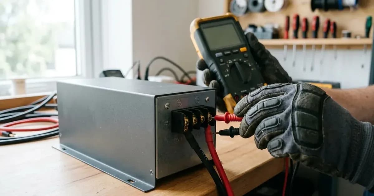
- Observation: Check battery bank DC terminal voltage with a multimeter. Listen for repeated internal relay clicking with flashing LCD and LEDs upon power-on.
- Meaning: Repeated internal relay clicking on and off with flashing LCD and LEDs indicates the battery is disconnected. If the battery voltage drops below 1.91 V per cell (<22.9 V on a 24V bank or <45.8 V on a 48V bank), the unit shuts down automatically during startup process (LCD/LEDs and buzzer active for 3 seconds). If battery voltage is far too low below 1.4 V per cell (<16.8 V on a 24V bank or <33.6 V on a 48V bank) or polarity is reversed, the inverter displays no response with a blank screen.
- Action: Always kill power first and use insulated tools before tightening battery terminals, because a metal spanner across a battery bank shorts hundreds of amps. If the battery bank is deeply discharged, recharge it with an external charger before reconnecting.
Cause/fix table section
Symptom detail | Likely cause | Fix |
|---|---|---|
Ziewnic inverter not charging battery from solar during daylight | Incorrect Charger Source Priority in Program 16 | Set Program 16 to |
Inverter not charging battery from WAPDA grid | Program 16 set to | Set Program 16 to |
Solar charging fails to initiate despite clear sunlight | Solar array DC voltage outside inverter MPPT operating window | Check array DC voltage on LCD. Ensure string voltage is within model limits (55-430 VDC for Diamond II 6G, 90~450 VDC for Diamond 5G, 120~500VDC for Roux, 125 - 430 VDC / 200 - 650 VDC for Lenox). |
Battery charges very slowly from solar or grid | Maximum charging current in Program 02 or Program 11 set too low | Increase Program 02 (Maximum charging current, 10A to 100A / 120A) and Program 11 (Maximum utility charging current) to match battery bank charging capacity. |
Inverter displays Fault 04 (Battery voltage is too low) or Warning 04 (Low battery) | Deeply depleted battery bank or Program 29 low DC cut-off threshold mismatch | Verify Program 29 (Low DC cut-off voltage, default 21.0 V for 24V, 42.0 V for 48V). If battery voltage is below 1.91 V per cell (<22.9 V on 24V, <45.8 V on 48V), unit shuts down after 3 seconds; recharge battery externally. |
Inverter displays Fault 03 (Battery voltage is too high) or Warning 03 (Battery is over-charged) | Incorrect bulk or float voltage parameters in Program 26 / 27 | Verify Program 26 (Bulk charging voltage, default 28.2 V for 24V, 56.4 V for 48V [AGM]) and Program 27 (Floating charging voltage, default 27V for 24V, 54V for 48V [AGM]) against manufacturer battery specifications. Note: 56.4V is suitable for 16-cell LiFePO4, but may overcharge 15-cell LiFePO4 packs. |
Lithium battery not charging or communicating with inverter | Incorrect Battery Type in Program 05 or BMS communication lost | Set Program 05 to |
Grid charging disconnects during low utility voltage swings | Program 03 set to | Change Program 03 (AC input voltage range) from |
Internal relay clicks repeatedly on and off with flashing LCD/LEDs | Battery cabling loose or DC fuse disconnected | Disconnect AC and PV supplies, wait at least 5 minutes, use insulated tools to securely tighten battery terminal connections, and inspect DC fuses. |
Inverter screen completely blank with no response on power on | Battery voltage far too low (<1.4 V per cell) or reversed DC polarity | Check DC polarity on battery terminals. If battery voltage is <16.8 V on 24V (<33.6 V on 48V), recharge batteries externally before attempting startup. |
Inverter and Battery-Side Checks
Troubleshooting battery charging issues requires verifying both internal firmware settings on the inverter and the physical state of the battery bank.
Inverter-Side Checks (Settings)
Most Ziewnic inverters—including the Axpert Ultra, Axpert Twin Premium +, Diamond, and Max series—are built on the Voltronic Power OEM platform. They share a standardized program menu architecture (Programs 01 to 36+). The Lenox series (touch-screen hybrid, Solarman monitoring) and Roux series (touch-screen display) use different menu systems and code schemes — the numbered programs, 2-digit fault/warning codes, and LED indicators in this guide do not apply to them; use their touch-screen settings menus to find the equivalent charger-priority and charge-current parameters.
- Program 16: Charger source priority
-
CSO(Solar first): Solar energy will charge battery as first priority. Utility will charge battery only when solar energy is not available. -
CUT(Utility first): Utility will charge battery as first priority. Solar energy will charge battery only when utility power is not available. -
SNU(Solar and Utility, default): Solar energy and utility will charge battery at the same time. Recommended during Pakistani load-shedding seasons. -
OSO(Only Solar): Solar energy will be the only charger source no matter utility is available or not. - Action: For active solar charging, ensure Program 16 is set to
CSOorSNU.
-
- Program 01: Output source priority
- Options:
USB(Utility first),SUB(Solar first, utility second, battery third),SBU(Solar first, battery second, utility third). InSUBmode with weak solar, all PV power goes directly to connected AC loads, leaving none for battery charging. - Action: If battery charging is required during daytime load operation, switch from
SUBtoSBUor reduce continuous AC load consumption.
- Options:
- Program 02: Maximum charging current
- Sets total combined charging current from solar and AC chargers: 10A to 100A / 120A.
- Action: For lead-acid tubular batteries, configure to 10%–15% of battery Ah rating (e.g., 20A–30A for 200Ah). For lithium batteries, configure according to BMS specifications up to 100A or 120A.
- Program 03: AC input voltage range
- Options:
APL(Appliance: 90-280VAC) andUPS(170-280VAC). - Action: Select
APLto prevent grid charging disconnection during low-voltage grid dips on WAPDA lines.
- Options:
- Program 05: Battery type
- Options:
AGM(default),FLD(Flooded/Tubular),USE(User-Defined),PYL(Pylontech),Lib(Lithium). - Action: Select
FLDfor Pakistani tubular batteries (Phoenix, Osaka, AGS, Volta). SelectPYLorLibfor lithium batteries with BMS communication. SelectingPYL/Libauto-configures charge voltages and switches cut-offs to SOC percentage.
- Options:
- Program 11: Maximum utility charging current
- Controls maximum charging rate from utility grid (default 30A).
- Action: Set between 15A–30A for tubular batteries to prevent electrolyte boiling, or up to 60A–80A for fast-charging lithium packs.
- Program 26: Bulk charging voltage (C.V voltage)
- Default is 28.2 V for 24V models and 56.4 V for 48V models [AGM]; adjust for Flooded/Tubular or custom Lithium. Note: 56.4V is suitable for 16-cell LiFePO4, but may overcharge 15-cell LiFePO4 packs.
- Action: Match this threshold with your battery manufacturer's absorption charge specification.
- Program 27: Floating charging voltage
- Default is 27V for 24V models and 54V for 48V models [AGM]; adjust for Flooded/Tubular or custom Lithium.
- Action: Match this maintenance trickle charge voltage with manufacturer recommendations.
- Program 29: Low DC cut-off voltage
- Default is 21.0 V for 24V models and 42.0 V for 48V models.
- Action: For flooded tubular batteries, ensure this cut-off is configured appropriately to protect cells from deep discharge and plate sulfation.
- Battery Equalization Settings (Programs 30, 31, 33, 34, 35, 36): Equalization drives cells into the explosive hydrogen gassing region, requiring active cross-ventilation away from sparks and flames (mandatory disabled
EdSfor lithium). - Program 30:
EEN(Enable) for Flooded/Tubular;EdS(Disable) mandatory for Lithium / Gel. - Program 31: Battery equalization voltage (default 58.4 V for 48V models; setting range 48.0V to 61.0 V).
- Program 33: Battery equalized time (default 60min; setting range 5min to 900min).
- Program 34: Battery equalized timeout (default 120min).
- Program 35: Equalization interval (default 30 days; setting range 0 to 90 days).
- Program 36:
AENto trigger manual desulfation cycle immediately in float stage. - Safety Warning: During battery equalization (Program 30/31 at 29.2 V / 58.4 V), flooded lead-acid batteries emit explosive hydrogen and oxygen gas. The battery compartment must have positive cross-ventilation away from sparks and flames. Never equalize sealed lithium or AGM/gel batteries.
- Program 30:
Battery-Side Checks (Hardware & Health)
- Physical Terminal Connections and Isolation:
- Inspect DC battery terminals for loose connections or acid corrosion.
- Always kill power first and isolate the DC breaker before servicing battery terminals, using insulated tools because an accidental spanner short across battery terminals releases hundreds of amps.
- Battery Voltage Threshold Triage:
- Measure open-circuit bank voltage with a calibrated DC multimeter.
- If battery bank voltage drops below 1.91 V per cell (<22.9 V on 24V or <45.8 V on 48V), the inverter shuts down automatically during startup after 3 seconds.
- If battery bank voltage drops below 1.4 V per cell (<16.8 V on 24V or <33.6 V on 48V) or polarity is reversed, the inverter displays no response with a blank screen. Deeply discharged banks must be jump-charged with a bench charger.
- Lead-Acid Battery Maintenance:
- For flooded tubular batteries, inspect electrolyte levels and specific gravity. Wear eye protection when testing electrolyte or opening cell vent caps, and add only distilled or demineralized water, never tap water and never acid. For brand-specific parameters, consult our Exide Battery Charging Voltage Settings Guide and Phoenix Battery Low Gravity Revival Steps.
- BMS Communication for Lithium Batteries:
- Verify the RJ45 communication link between the lithium battery BMS and inverter BMS port.
- Ensure the BMS RS485 communication baud rate is configured to 9600 bps (Dip 1 is “ON”). Direct pass-through Ethernet cables must not be used without confirming the correct pin assignment (PIN 3/5 for RS485, PIN 6/7 for CAN). For detailed pinouts, see Lithium Battery Inverter Compatibility Errors and MaxPower Lithium BMS Fault Comms Fix.
Safety: High Voltage and Chemical Hazards
Troubleshooting solar inverters and battery storage banks involves severe electrical, thermal, and chemical hazards:
- High-Voltage DC Shock Hazard: Solar array open circuit voltages reach up to 450VDC / 500VDC on single-phase models (Diamond, Axpert, Max, Roux) and up to 800VDC on three-phase hybrid models (Lenox 12kW). High DC voltages create lethal electric shock hazards and persistent DC arcing risks.
- Internal Capacitor Stored Energy Discharge: High-voltage DC bus capacitors store significant electrical charge. Installers and service technicians must wait at least 5 minutes after disconnecting all solar PV, battery DC, and AC grid supplies before removing enclosure panels or servicing terminal blocks.
- Battery Terminal Short-Circuit Risks: Battery banks can deliver hundreds of amperes of instantaneous fault current. Always kill power first, isolate DC disconnects, and use insulated tools when servicing battery terminals to prevent explosive arcing and severe burns.
When to call a technician instead
While most charging faults stem from misconfigured settings or tripped breakers, hardware failures require certified service:
- Internal Component Failures: Inverter fault codes Fault 08 (Bus voltage is too high), Fault 09 (Bus soft start failed), Fault 53 (Inverter soft start failed), or Fault 57 (Current sensor failed) indicate internal component failures that require return to an authorized repair center.
- Damaged MPPT Charge Controller: If PV array open-circuit voltage is within operating range but PV input current and wattage remain at 0 on LCD in full sunlight, the internal MPPT boost stage or charge controller fuse may be damaged.
- Severe Battery Degradation: Swollen, cracked, or boiling battery casings indicate internal short-circuits or thermal runaway requiring immediate decommissioning.
- Warranty Repairs: Ziewnic offers a 5-Year PCBA replacement warranty on flagship hybrid lines (Lenox) and standard 3 to 5-year warranties on retail models. Unauthorized board repairs void warranty coverage.
- Authorized Service Centers: Ziewnic operates authorized service facilities in Karachi (Office # 5, 2nd floor, Above Meezan Bank, Rehman Mansion, Regal Chowk, Sharah-e-Liaquat, Saddar) and Lahore (51 Justice M. Akram (Mozang) Road, Near Masjid-e-Nimra, Near Saffa Wala Chowk).
For additional background on inverter lineages and rebadging across Pakistan, see our guide on Chinese vs Local Brand Inverters and our Inverter Error Code Glossary.
Still showing the fault? Book a technician
If the steps above did not clear it, tell us the inverter or battery and the exact code. We pass it to a technician who covers your city; visit charges are quoted before they come.
How this pays for the site: the technician or verifier pays SolarNevs a fixed introduction fee. Nobody pays to be recommended, and you are free to use our free guides instead.
Frequently asked questions
Why is my Ziewnic inverter not charging the battery from solar?
The most common reasons are incorrect charging source priority (Program 16 on Axpert/Diamond/Max models) (CSO or SNU required), solar PV input voltage outside the inverter's MPPT operating window, or a restricted maximum charging current in Program 02. Verify these parameters on the inverter display first.
What is the correct MPPT voltage range for Ziewnic inverters?
MPPT operating ranges vary across Ziewnic series. Diamond II 6G models operate between 55-430 VDC, Diamond 5G models require 90~450 VDC, Roux series inverters operate between 120~500VDC, and Lenox series models range from 125 - 430 VDC on single-phase to 200 - 650 VDC on three-phase. Ensure your solar array string voltage falls within your specific model's MPPT window.
How do I enable grid charging on my Ziewnic inverter?
To enable utility grid charging, set Program 16 (Charger source priority) to `CUT` (Utility first) or `SNU` (Solar and Utility). Setting `SNU` allows both solar PV and utility grid to charge the battery bank simultaneously, which is recommended during load-shedding seasons.
What Ziewnic inverter settings are important for lithium batteries?
For lithium batteries, set Program 05 (Battery type) to `PYL` (Pylontech) or `Lib` (Lithium). Selecting `PYL` or `Lib` auto-configures charge voltages and switches cut-offs to SOC percentage. Always disable battery equalization (Program 30 set to `EdS`) for lithium batteries.
My Ziewnic inverter shows a low battery warning but isn't charging. What should I do?
A low battery warning (Warning 04) indicates the battery voltage is approaching the low DC cut-off threshold. Verify Program 16 allows charging from solar (CSO) or grid (SNU). If the battery voltage is critically low (below 1.91 V per cell, or <22.9 V for a 24V bank / <45.8 V for a 48V bank), the inverter may shut down automatically during startup. Before any physical inspection of battery terminals or wiring, ALWAYS disconnect all AC, PV, and battery power sources, wait at least 5 minutes for internal capacitors to discharge, and use insulated tools. Unauthorized physical intervention may void your warranty.
References
- Ziewnic Diamond II Series PV3000/PV4500 product data sheet (PDF) — MPPT range 55-430 VDC, max PV open-circuit 430 VDC, 80A charge current, 5-year warranty — accessed 6 September 2026
- Ziewnic Diamond 5G PV6500 hybrid inverter product page — MPPT 90~450 VDC, start-up 90/120 VDC — accessed 6 September 2026
- Ziewnic Axpert Twin Premium Plus PV5000 product page — MPPT 90-450 VDC, PV input from 30 VDC, max PV 450 VDC — accessed 6 September 2026
- Ziewnic Roux-X-LV4.7 product page — MPPT tracking range 120~500 VDC, max PV input 500 VDC, 100A charge current — accessed 6 September 2026
- Ziewnic Lenox 3.0 10kW single-phase hybrid (PV16000) product page — MPPT 125-430 V, max DC 500 V — accessed 6 September 2026
- Ziewnic Lenox 3.0 L-TP-Hybrid 12kW/16kW three-phase product data sheet (PDF) — MPPT 200-650 V, max DC 800 V, 5-year PCBA replacement warranty — accessed 6 September 2026
- Ziewnic service centre directory — Karachi and Lahore service centre and head-office addresses — accessed 6 September 2026
Related guides
More from inverter errors & fixes.