Victron Cegasa eBick Battery Setup Guide
Updated 6 September 2026 · By SolarNevs Research Desk, Dealer surveys + verified sources · 2 sources · Method ↗
Key Takeaways
- A Victron GX device and BMS-Can connection are mandatory for Cegasa eBick LV batteries.
- Correct VEConfigure settings, including absorption voltage (52.2 V) and charge current (140A per module), are critical.
- Victron systems do not support Cegasa high voltage configurations beyond 48V nominal.
- Always ensure all Victron components have the latest compatible firmware before setup.
How do I set up Cegasa eBick LV batteries with a Victron Energy system?
Setting up Cegasa eBick LV batteries with a Victron Energy system requires specific hardware, firmware, and configuration steps to ensure proper communication and operation. The most common cause of setup issues is incorrect wiring or missing essential VEConfigure settings. The first thing to check is that you have a Victron GX device connected via BMS-Can.
Diagnosis and Setup Steps
Follow these steps to diagnose common setup issues and correctly configure your Victron system with Cegasa eBick LV batteries.
- Verify GX Device Requirement:
- Check: Confirm you have a Victron GX device, such as a Cerbo GX.
- Meaning: A GX device is essential for managing communication between the Cegasa battery's external BMS and the Victron system. Using a CCGX is not recommended due to its single VE.Can port.
- Action: If you do not have a GX device, acquire one before proceeding.
- Check Firmware Versions:
- Check: Verify the firmware version of your GX device and inverter/charger.
- Meaning: The GX device requires a minimum firmware version of v2.22. Inverter/charger units need a minimum firmware version of 469. Outdated firmware can cause communication failures or incorrect operation.
- Action: Update all Victron components to their latest recommended firmware versions.
- Confirm BMS-Can Connection:
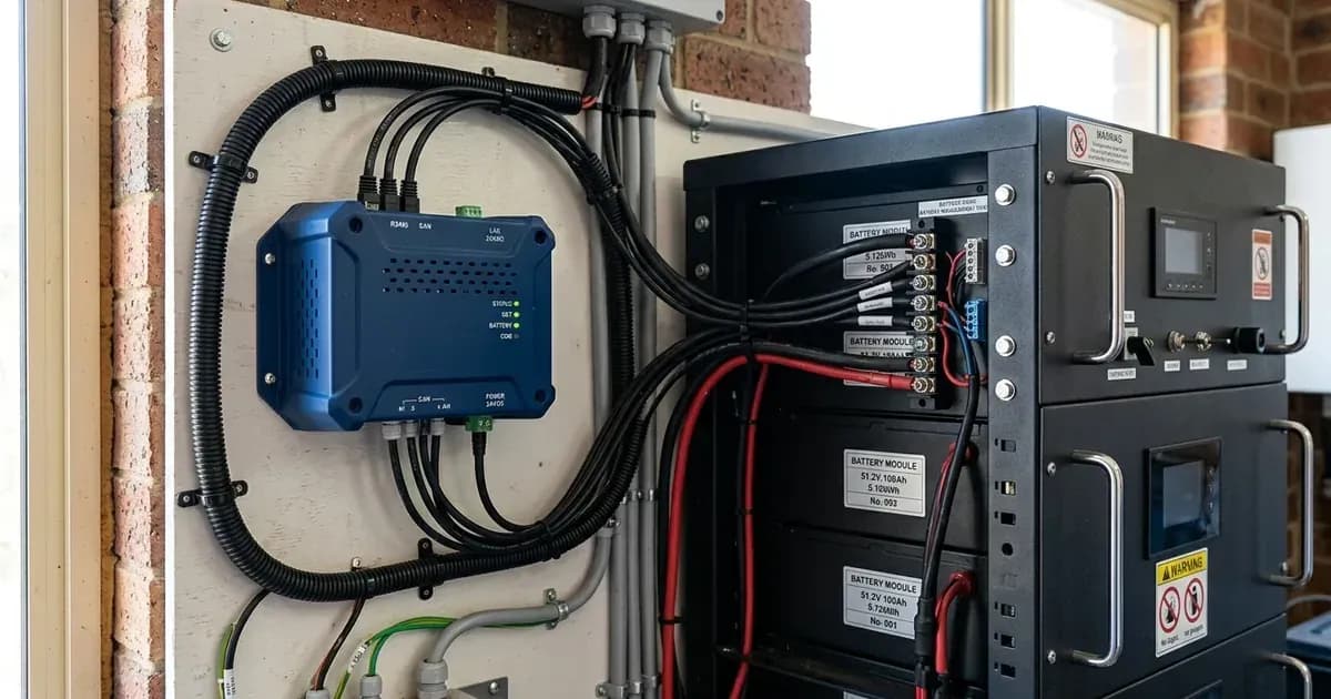
- Check: Ensure a standard CAT5e or CAT6 network cable connects the Cegasa eBick LV's external BMS (MCS master box) to the BMS-Can port of the GX device.
- Meaning: This connection is crucial for the communication of charge and discharge limits, error codes, and the battery's State of Charge (SoC). The specially wired Victron BMS cables (Type A or B) are not used with the Cegasa BMS.
- Action: Connect the cable and ensure a VE.Can terminator (supplied with the GX device) is connected to the other BMS-Can port on the GX device. Power on the GX device and verify the battery appears in the GX device menus. For more details on this communication protocol, refer to our guide on understanding-bms-can-communication.
- Configure Inverter Type in Cegasa BMS:
- Check: Confirm the inverter type is configured in the Cegasa BMS via the Cegasa EViewer WebApp.
- Meaning: This initial configuration within the battery's own system is a prerequisite for proper integration with Victron.
- Action: Refer to your Cegasa documentation for specific instructions on using the EViewer WebApp to set the inverter type.
- Verify Inverter/Charger Connection:
- Check: Ensure your Victron inverter/charger (Multi, MultiPlus, Quattro, or RS model) is connected to the GX device via the VE.Bus connection port.
- Meaning: All 48V Multis, MultiPlusses, MultiGrids, Quattros, and RS models are compatible. This connection allows the GX device to control the inverter/charger based on battery data.
- Action: Confirm the physical VE.Bus connection.
- Check Solar Charger Connection:
- Check: Ensure all current model 48V BlueSolar, SmartSolar VE.Direct, and MPPT RS solar chargers are connected to the GX device.
- Meaning: Connection to the GX device is mandatory for solar chargers, as the GX device uses battery data to regulate charge currents and voltages from the solar input.
- Action: Connect solar chargers to the GX device. If using VE.Can for solar chargers, ensure your GX device has sufficient CAN-Bus ports.
- Configure VEConfigure Settings:
- Check: Review the VEConfigure settings for your inverter/charger to match the recommended values for Cegasa eBick LV batteries.
- Meaning: Incorrect settings can lead to improper charging, reduced battery lifespan, or system shutdowns.
- Action: Apply the settings detailed in the table below. For a comprehensive guide on Victron GX device configuration, see our article on victron-gx-device-configuration.
Troubleshooting Common Issues
Symptom detail | Likely cause | Fix |
|---|---|---|
BMS triggering over-current alarms, and system shutdowns | Using very large solar arrays with battery banks that are too small, exceeding the battery's charge limits. | Ensure your battery bank capacity is appropriately sized for your solar array and load. Review the "Minimum Battery Modules Required" table below. |
Battery not appearing in GX device menu | Incorrect or missing BMS-Can connection, outdated GX device firmware, or inverter type not configured in Cegasa BMS. | Verify BMS-Can wiring, ensure VE.Can terminator is installed, update GX device firmware to v2.22 or later, and configure inverter type in Cegasa EViewer WebApp. |
Inverter/charger not charging or discharging correctly | Incorrect VEConfigure settings, or outdated inverter/charger firmware. | Update inverter/charger firmware to 469 or later. Apply correct VEConfigure settings for Absorption voltage, Float voltage, and Charge Current as specified. |
Solar chargers not regulating charge to battery | Solar chargers not connected to the GX device, or outdated solar charger firmware. | Connect all solar chargers to the GX device. Ensure solar chargers have the latest firmware. |
System instability or unexpected shutdowns | General communication issues between components, or incorrect battery capacity setting. | Verify all communication cables (BMS-Can, VE.Bus) are secure. Ensure the total battery capacity is correctly entered in VEConfigure (e.g., 280Ah times the number of modules for eBick LV). |
Victron System Configuration for Cegasa eBick LV
Proper configuration of your Victron inverter/charger via VEConfigure is essential for the safe and efficient operation of your Cegasa eBick LV batteries. These settings ensure the battery is charged and discharged within its specified parameters.
VEConfigure Settings for Cegasa eBick LV (Normal Operation with DVCC)
Setting Name | Values | Protocol |
|---|---|---|
Enable battery monitor | Checked | VEConfigure |
Battery capacity | Total capacity of the battery: eg 280Ah times the number of battery modules | VEConfigure |
Charge Efficiency | 95% | VEConfigure |
Battery type | Lithium | VEConfigure |
Charge curve | Adaptive | VEConfigure |
Absorption voltage | 52.2 V | VEConfigure |
Float voltage | 52 V | VEConfigure |
Absorption time | 8 Hr | VEConfigure |
Charge Current | 140A per battery module | VEConfigure |
DC input low shut-down | 44V | VEConfigure |
DC input low restart | 48V | VEConfigure |
DC input low pre-alarm | 45V | VEConfigure |
Minimum Battery Modules Required - Cegasa eBick LV
This table indicates the minimum number of Cegasa eBick LV modules required for various Victron inverter/charger models and system configurations (ESS for Energy Storage Systems, Off-grid for standalone systems). These are minimums; larger systems may require more modules.
Inverter/Charger | Phases | ESS | Off-grid |
|---|---|---|---|
Multiplus & Multiplus II & MP-II GX 48/3000/35 | Single Phase | 1 | 1 |
Multiplus & Multiplus II & MP-II GX 48/3000/35 | Three Phase | 1 | 2 |
Multiplus & Multiplus II & MP-II GX 48/5000/70 | Single Phase | 1 | 1 |
Multiplus & Multiplus II & MP-II GX 48/5000/70 | Three Phase | 2 | 2 |
Inverter RS & Multi RS 48/6000 | Single Phase | 1 | 1 |
Inverter RS & Multi RS 48/6000 | Three Phase | ||
Quattro 48/5000/70-100/100 | Single Phase | 1 | 1 |
Quattro 48/5000/70-100/100 | Three Phase | 2 | 2 |
Quattro 48/8000/110-100/100 | Single Phase | 1 | 1 |
Quattro 48/8000/110-100/100 | Three Phase | 3 | 3 |
Quattro 48/10000/140- 100/100 | Single Phase | 1 | 2 |
Quattro 48/10000/140- 100/100 | Three Phase | 3 | 4 |
Quattro 48/15000/200- 100/100 | Single Phase | 2 | 2 |
Quattro 48/15000/200- 100/100 | Three Phase | 6 | 6 |
EasySolar & EasySolar-II 48/3000/35-50 MPPT | Single Phase | 1 | 1 |
EasySolar & EasySolar-II 48/3000/35-50 MPPT | Three Phase | 1 | 2 |
EasySolar 48/5000/70-100 MPPT | Single Phase | 1 | 1 |
EasySolar 48/5000/70-100 MPPT | Three Phase | 2 | 2 |
Cegasa eBick LV and eBick LV 15 Battery Specifications
The Cegasa eBick LV and eBick LV 15 are low-voltage lithium batteries designed for compatibility with Victron systems.
Model | Ratings |
|---|---|
EBick LV | Module capacity: 13.5 kWh |
EBick LV | Module limit: 20 |
EBick LV | Max capacity: 270 kWh |
EBick LV | Approximately 280Ah at 48V (52.2V maximum) |
EBick LV 15 | Module capacity: 15 kWh |
EBick LV 15 | Module limit: 20 |
EBick LV 15 | Max capacity: 300 kWh |
EBick LV 15 | Approximately 314Ah at 48V (52.2V maximum) |
Note that Victron systems do NOT support the series connection configuration for Cegasa eBick 280 Pro series, which limits the maximum capacity to 18 modules.
Cegasa E/Scal 6 High Voltage Battery Note
The Cegasa E/Scal 6 is a high voltage battery module. Victron Energy states that their systems are not compatible with the Cegasa high voltage configuration where battery voltage is increased beyond 48V nominal. For setup instructions and compatibility details regarding the Cegasa E/Scal 6, you must contact the battery manufacturer directly.
Safety: Working with Lithium Batteries and High-Voltage DC Systems
Working with lithium iron phosphate (LiFePO4) batteries and high-voltage DC systems requires strict adherence to safety protocols.
- Disconnect Power: Always isolate all power sources (PV, battery, AC breakers) before working on any components. Wait the manual's specified capacitor-discharge time for inverters.
- Insulated Tools: Use only insulated tools when working with battery terminals or electrical connections to prevent short circuits. A spanner across a battery bank can short hundreds of amps, causing severe burns or equipment damage.
- Personal Protective Equipment (PPE): Wear appropriate PPE, including safety glasses and insulated gloves, when handling batteries or making electrical connections.
- Ventilation: Ensure adequate ventilation in the battery area. While LiFePO4 batteries are generally safer than other chemistries, proper airflow helps manage temperature.
- BMS Protection: Lithium batteries rely on their Battery Management System (BMS) for protection against overcharge, over-discharge, over-current, and extreme temperatures. Do not bypass or tamper with the BMS. For more information on maintaining your battery system, consult our lifepo4-battery-care-and-maintenance guide.
- Authorized Service: Opening the battery enclosure or internal components is generally authorized-service work. Do not attempt to repair internal battery components yourself.
When to call a technician instead
While many setup and troubleshooting steps can be performed by a competent DIY installer, there are clear limits. You should call a qualified solar technician or Victron installer if:
- You are unsure about any wiring diagrams or electrical connections.
- The system displays persistent errors or alarms that you cannot resolve using the provided troubleshooting steps.
- You need to perform tasks that involve opening battery enclosures or internal inverter components, as this can void warranties and pose significant safety risks.
- You are dealing with high voltage systems (like the Cegasa E/Scal 6) where Victron explicitly states incompatibility beyond 48V nominal, and the manufacturer's specific setup instructions are required.
- The system is not performing as expected after all settings have been verified, indicating a potential hardware fault.
Frequently asked questions
What Victron hardware is required for Cegasa eBick LV batteries?
A Victron GX device (e.g., Cerbo GX), a compatible 48V Victron inverter/charger (Multi, MultiPlus, Quattro, RS models), and compatible 48V Victron solar chargers (BlueSolar, SmartSolar VE.Direct, MPPT RS) are required. The GX device facilitates communication between the battery BMS and the Victron system.
What firmware versions are needed for Victron components when using Cegasa eBick batteries?
The GX device requires a minimum firmware version of v2.22, though the latest version is recommended. Inverter/charger units need a minimum firmware version of 469, with updates to the latest version also recommended for optimal compatibility and performance.
What are the key VEConfigure settings for Cegasa eBick LV batteries?
Essential VEConfigure settings include enabling the battery monitor, setting battery capacity (e.g., 280Ah per module), Charge Efficiency to 95%, Battery type to Lithium, Charge curve to Adaptive, Absorption voltage to 52.2 V, Float voltage to 52 V, Absorption time to 8 Hr, and Charge Current to 140A per battery module. DC input low shutdown, restart, and pre-alarm values should also be configured.
How do Cegasa eBick batteries communicate with Victron systems?
Cegasa eBick LV batteries communicate with Victron systems via the BMS-Can port on a Victron GX device. An external BMS (MCS master box) on the eBick LV connects directly to the GX device using a standard CAT5e or CAT6 network cable. This connection is vital for managing charge/discharge limits, error codes, and State of Charge (SoC).
Is the Cegasa E/Scal 6 (High Voltage) battery compatible with Victron systems?
Victron systems are not compatible with the Cegasa high voltage configuration where battery voltage is increased beyond 48V nominal. For setup instructions regarding the Cegasa E/Scal 6, you must contact the battery manufacturer directly.
References
- Victron & Cegasa Battery Compatibility — accessed 23 August 2026
- Victron HV Battery Compatibility: Cegasa E/Scal 6 — accessed 23 August 2026
Related guides
More from what to buy — and how not to get cheated.