Solis Inverter 1033 PV ISO PRO Alarm: DC Isolation Fault Triage
Updated 18 September 2026 · By SolarNevs Research Desk, Dealer surveys + verified sources · 1 source · Method ↗
Key Takeaways
- Alarm code 1033 PV ISO PRO signals that solar array DC insulation resistance to earth has dropped below the inverter safety threshold.
- The ground fault will need to be resolved before the system can be energized or the inverter will be damaged by it.
- Sub-codes identify fault polarity: negative wire is connected to ground (sub-code 01) or positive wire is connected to ground (sub-code 02).
- Always shut down the system and disconnect both AC and DC supplies before disconnecting DC string connectors to prevent lethal electrical shock and direct-current arc flashes.
Why is my Solis inverter showing PV ISO PRO?
When morning dew settles on the roof or persistent British rainfall penetrates solar module backsheets, Solis inverters perform an automated pre-startup insulation resistance test. If the detected impedance falls below protective safety boundaries, the inverter locks out generation and displays alarm code 1033.
In official manufacturer service documentation, this condition means the resistance in DC side (solar) is too low on one or more strings. Leaving a ground fault unresolved presents severe risks: the ground fault will need to be resolved before the system can be energized or the inverter will be damaged by it.
Understanding the root cause requires isolating whether the fault lies within internal inverter circuitry or across external rooftop string conductors. For broader inspection standards on British commercial and domestic arrays, see our UK solar electrical inspection guide.
Polarity sub-codes: negative vs positive ground faults
Solis inverters identify which polarity conductor has shorted to the grounded mounting frame:
- PV ISO-PRO01: Indicates that the negative wire is connected to ground. This commonly points to pinched negative return cables under panel racking or water penetration inside a negative DC isolator enclosure.
- PV ISO-PRO02: Indicates that the positive wire is connected to ground. This indicates an insulation breakdown on the positive array feeder, requiring immediate isolation to eliminate electrical shock hazards.
Testing internal inverter terminal resistance
Before climbing onto the roof to inspect solar panels, technicians must verify whether the internal isolation barrier of the inverter has failed:
- Complete Electrical Isolation: Completely isolate the inverter from all energy sources by opening both the external AC circuit breaker and the DC rotary switches.
- Remove Field Connections: Remove all of the DC strings and AC wires from the underside of the inverter chassis.
- Test Positive Terminal to Earth: Turn on the DC switch that was on the inverter; then measure the resistance of all DC+ and earth (put the red pin of the multi-meter into the DC+ terminals and the black pin of the multi-meter to the heat sink).
- Test Negative Terminal to Earth: And then measure the resistance of all DC- and earth (put the red pin of the multi-meter into the DC- terminals and the black pin of the multi-meter to the heat sink).
If low resistance is measured directly to the heat sink with all external strings removed, the internal inverter surge suppression or inverter bridge is shorted and requires replacement.
String-by-string isolation procedure
If internal inverter terminals show normal high resistance to the chassis heat sink, the fault is located in the external array wiring. Follow this sequential string isolation method:
- System Cooldown: Shut down the whole system for 5 minutes to ensure all internal capacitors have fully discharged.
- Disconnect All Strings: Take off all of the PV strings from the bottom DC input terminals.
- Single String Connection: Then input one of the PV strings to the inverter.
- Five-Minute Trial Run: Switch on the inverter(with Grid on) for 5 minutes.
- Alternate Strings: If there is no alarm, shut off the whole system and pull the PV string off the inverter; then swap another PV string to the inverter.
- Identify Faulted Circuit: Cycle this and check under which PV string the alarm will occur.
- Inspect Array Wiring: Once the faulty string is isolated, carefully examine that PV string to see if there are any ground problems, such as damaged insulation, pinched conductors under racking clamps, waterlogged junction boxes, or cables resting on wet roof tiles.
For wiring safety rules across British installations, consult our UK solar electrical installation guide.
Multimeter voltage decay diagnostic method
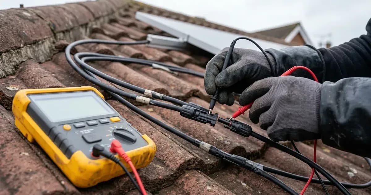
To confirm a ground fault without energizing the inverter, electricians conduct a open-circuit voltage decay test using a digital multimeter:
- Use a multi-meter to check the voltages between PV+ and earth, as well as between PV- and earth across all disconnected array strings.
- On a healthy, ungrounded solar circuit, electrostatic charge should bleed off: it should be decreasing from a certain value between 5% of Voc and 95% of Voc.
- If the measured voltage to earth remains constant rather than decaying, a solid electrical fault exists between that conductor and the grounded roof frame.
- Record all findings: please tell us all the values showing in the running messages in the advanced info of the LCD when submitting diagnostic records to technical support.
Ensuring array health protects generation revenue and export metering under the Smart Export Guarantee scheme.
Safety rules for DC isolation troubleshooting
Direct-current electricity does not exhibit natural zero-crossing points, creating continuous arc flash hazards if handled incorrectly.
- Never Disconnect Under Load: Never unplug MC4 connectors while the array is generating current; always open the AC breaker and rotate the DC isolator to OFF before touching DC terminals.
- Insulated Hand Tools: Only use insulated tools and certified multimeter leads rated for photovoltaic testing.
- Capacitor Discharge Time: Always respect the mandatory 5 minutes cooldown period before opening enclosures or touching terminal blocks.
- Wet Weather Precautions: Moisture lowers array insulation resistance; avoid working on wet roofs where slipping hazards and shock conductivity are elevated. For grid connection compliance, review our ENA EREC G98 micro-generator guide.
When to call an MCS-certified solar installer
DC isolation faults involve live direct-current circuits that cannot be switched off at source during daylight hours. Escalate to a certified installer if:
- The inverter displays PV ISO PRO immediately upon startup even in dry weather.
- Visual inspection reveals damaged or charred solar cables on the roof.
- String voltage decay measurements remain fixed, indicating a hard short to the building fabric.
- Inverter terminal resistance testing confirms an internal short circuit to the heat sink.
Frequently asked questions
What does PV ISO PRO mean on a Solis inverter?
PV ISO PRO means the resistance in DC side (solar) is too low on one or more strings. The ground fault will need to be resolved before the system can be energized or the inverter will be damaged by it.
What is the difference between PV ISO-PRO01 and PV ISO-PRO02?
PV ISO-PRO01 indicates that the negative wire is connected to ground. PV ISO-PRO02 indicates that the positive wire is connected to ground on the solar array DC circuit.
How do you identify which solar string is causing the isolation fault?
Shut down the system for 5 minutes, take off all of the PV strings, then input one of the PV strings to the inverter and switch on for 5 minutes. Swap another PV string to the inverter and cycle this to check under which PV string the alarm occurs.
How do you test string open-circuit voltage decay to earth?
Isolate power first to avoid shock, then use a multimeter to check the voltages between PV+ and earth. It should be decreasing from a certain value between 5% of Voc and 95% of Voc; a constant reading confirms a grounded conductor.
References
- Solis Service Center 1033 PV ISO PRO Diagnostic Guide — accessed 15 September 2026
Related guides
More from inverter errors & fixes.