Victron VE.Bus Error Codes: Troubleshooting MultiPlus and Quattro Systems
Updated 10 September 2026 · By SolarNevs Research Desk, Dealer surveys + verified sources · 1 source · Method ↗
Key Takeaways
- The most likely causes for VE.Bus errors are communication issues or imbalances within multi-phase systems.
- The first step in troubleshooting is to check device LEDs and your GX Device or VRM for specific alarm details.
- AC and DC voltages can be lethal. Only trained professionals should attempt complex troubleshooting or internal repairs.
- Stop DIY troubleshooting and contact Victron service if errors persist after basic checks, or if the error code specifically instructs you to do so.
What do Victron VE.Bus error codes mean on MultiPlus and Quattro inverters?
VE.Bus error codes indicate communication or system configuration issues within Victron MultiPlus, MultiPlus-II, and Quattro systems. These errors can prevent your inverter/charger from operating correctly. The most common causes relate to multi-phase system imbalances or incorrect cabling.
Diagnosis Steps
Follow these steps to diagnose common VE.Bus errors in your Victron system.
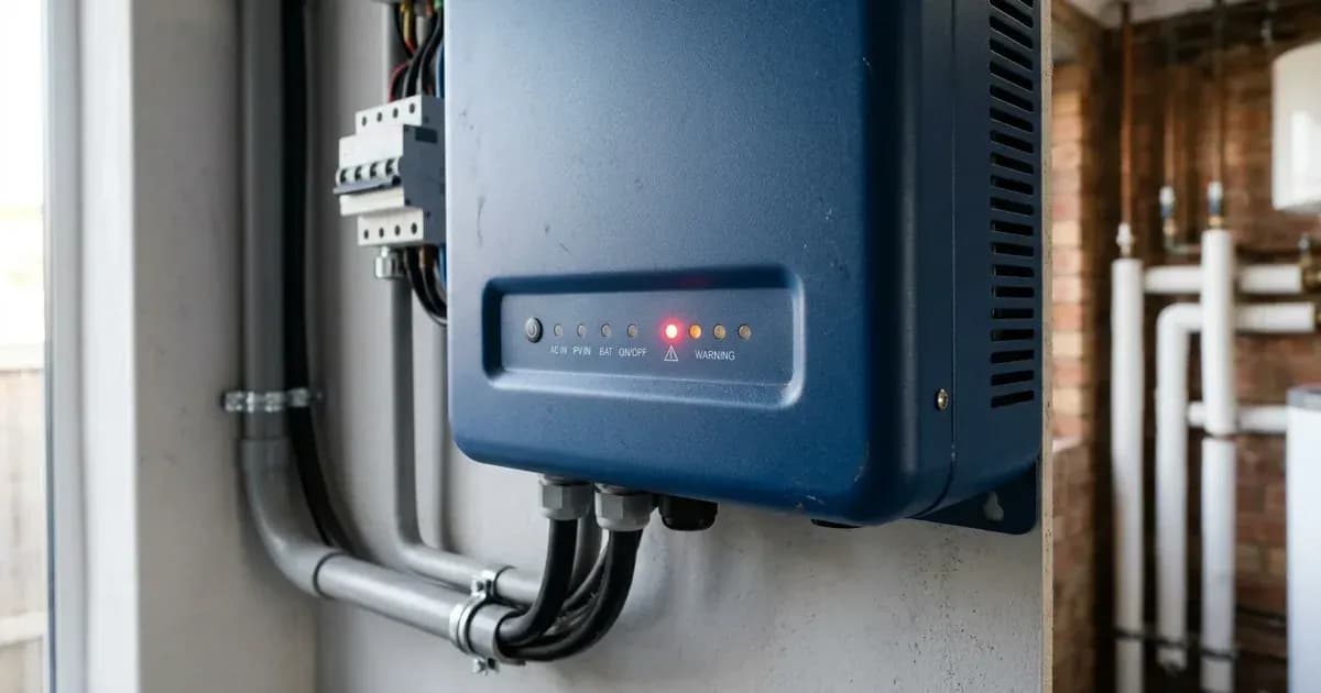
- Check Device LEDs: Observe the LEDs on your MultiPlus, MultiPlus-II, or Quattro unit. Look for indicators such as Overload, Low battery, or Temperature alarms, especially if VE.Bus Error 1 is present.
- Meaning: These LEDs can pinpoint the specific fault causing a phase to shut down in a multi-phase system.
- Consult GX Device or VRM: If you have a GX Device (e.g., Cerbo GX) or use Victron Remote Management (VRM), check the alarm status. VRM requires Automatic alarm monitoring to be enabled to log these errors.
- Meaning: The GX Device will indicate VE.Bus Error #1 and provide alarm status for each phase. VRM logs can show alarm history.
- Inspect Communication Cables: Examine all RJ45 VE.Bus communication cables connecting your devices. Ensure they are securely plugged in and undamaged.
- Meaning: Self-crimped or faulty cables are a common cause of various VE.Bus errors. Commercial patch leads are recommended for reliable communication.
- Check for Blown DC Fuses: In systems experiencing VE.Bus Error 3, inspect the DC fuses within the units.
- Meaning: A blown DC fuse can prevent a unit from communicating correctly, leading to Error 3.
Cause and Fix Table
Symptom detail | Likely cause | Fix |
|---|---|---|
VE.Bus Error 1 | One phase in a multi-phase system failed due to Low battery, Overload, or High temperature. | Identify the failing phase by checking LEDs or GX Device/VRM. Address the underlying alarm (e.g., reduce load, check battery state). |
VE.Bus Error 2 | New and old type MK2 protocol mixed in the system. | Contact Victron service for resolution. |
VE.Bus Error 3 | Improper system configuration (two separate VE.Bus systems connected). | Ensure all VE.Bus devices are configured as a single system. |
VE.Bus Error 3 | Communication cable error (e.g., hand-crimped cables). | Replace any self-crimped RJ45 cables with commercial patch leads. |
VE.Bus Error 3 | Blown DC fuse in one or more units. | Inspect and replace any blown DC fuses. |
Various VE.Bus errors | Using self-crimped RJ45 network cables. | Use commercial patch leads for all VE.Bus communication. |
System Configuration and Firmware Notes
Victron MultiPlus, MultiPlus-II, and Quattro devices communicate using the VE.Bus protocol. Correct configuration and up-to-date firmware are crucial for stable operation.
- System Restart Procedure: If you encounter a VE.Bus error, a system restart can sometimes resolve temporary communication glitches. To perform a system restart, switch all units off one by one. Then, switch all units on again using the On / Off / Charger-only rocker-switch on each device.
- Firmware Updates: Firmware updates are available for VE.Bus products and GX devices. These updates often include bug fixes and performance improvements. Certain settings and firmware updates require experience and training.
- VRM Monitoring: The Victron Remote Management (VRM) portal can provide valuable insights into your system's performance and history. Uploading data to VRM shows a log, and enabling Automatic alarm monitoring can help track Overload and Temperature errors that might lead to VE.Bus issues.
- GX Device Role: A GX Device (like a Cerbo GX) is essential for monitoring and managing complex Victron systems. It indicates VE.Bus Error #1 and provides alarm status for each phase, aiding in quick diagnosis.
Safety
Working with electrical systems carries inherent risks. AC and DC voltages can be lethal.
- Professional Assistance: The steps and instructions explained in this guide are intended to be carried out by trained professionals. Do not attempt any complex troubleshooting or repairs unless you are qualified.
- Power Isolation: Before inspecting any wiring or internal components, always ensure that all AC and DC power sources are completely isolated. This includes turning off PV, battery, and AC breakers. Wait for the manual's specified capacitor discharge time before proceeding.
- Insulated Tools: When working near electrical terminals, always use insulated tools to prevent accidental short circuits. A spanner across a battery bank can short hundreds of amps, causing severe burns or equipment damage.
When to call a technician instead
While basic troubleshooting can resolve many issues, some situations require professional intervention.
- Persistent Errors: If VE.Bus errors persist after performing the basic diagnostic steps and fixes, or if you are unable to identify the root cause.
- VE.Bus Error 2: This error specifically instructs you to contact Victron service, as it involves mixing MK2 protocol types.
- Internal Component Issues: If diagnosis points to a blown internal fuse, damaged wiring, or other internal component failure. Opening the unit for repair is authorized-service work.
- Lack of Experience: If you are not comfortable or experienced with electrical systems, it is always safer to consult a qualified Victron installer or technician. Attempting repairs without proper knowledge can void your warranty and pose significant safety risks.
Frequently asked questions
What does VE.Bus Error 1 mean on a Victron system?
VE.Bus Error 1 indicates that a device has switched off because one of the other phases in a multi-phase system has failed due to an Overload, Low battery, or Temperature alarm. You should check the device LEDs or your GX Device/VRM for specific alarm status.
How do I fix VE.Bus Error 2?
VE.Bus Error 2 signifies that new and old type MK2 protocols are mixed within the system. This issue typically requires contacting Victron service for resolution.
What causes VE.Bus Error 3?
VE.Bus Error 3 often follows VE.Bus Error 1 and can be caused by improper system configuration (e.g., two separate VE.Bus systems connected), communication cable errors, or a blown DC fuse in one or more units.
Can I use self-crimped RJ45 cables for VE.Bus communication?
No, using self-crimped RJ45 network cables is a commonly reported cause of various VE.Bus errors. For reliable communication, commercial patch leads are recommended.
How do I restart a Victron VE.Bus system?
To restart a Victron VE.Bus system, switch all units off one by one. Then, switch all units on again using the On / Off / Charger-only rocker-switch on each device.
References
- Victron Energy VE.Bus Error Codes — accessed 23 August 2026
Related guides
More from sizing, net billing & installation.