Solar Inverter Grid Voltage Trip in Ireland: High Voltage (OV-G-V) Solutions
Updated 19 September 2026 · By SolarNevs Research Desk, Dealer surveys + verified sources · 3 sources · Method ↗
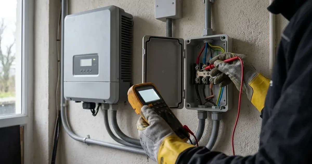
Key Takeaways
- Solar inverters trip on overvoltage (OV-G-V) when local AC voltage rises above the thresholds established under national grid interconnection rules.
- Tripping that occurs repeatedly as the system ramps up to 2000W indicates severe AC line impedance or undersized cable runs between the inverter and main board.
- Check voltage readings both on the inverter display and manually with a multimeter at the AC gland to pinpoint local resistive voltage rise.
- Working on live AC distribution circuits carries lethal shock risk; always isolate AC and DC supplies and hire a Safe Electric Registered Electrical Contractor.
Why is my solar inverter tripping on high grid voltage in Ireland?
A solar inverter trips on high grid voltage when the voltage at its AC output terminals exceeds the operating window programmed into its firmware. When the inverter generates electricity, it must push current back toward the consumer unit and utility transformer. This export current inevitably creates a voltage rise across the resistance of the interconnecting cables.
Ginlong Solis documentation explains that when an inverter ramps output, problems frequently emerge at specific thresholds:
- Generation Onset Trip: The inverter increase power up to 2000w and suddenly trip on ov g v1 error. This symptom points directly to local circuit impedance or bad terminations rather than broad utility fluctuations.
- Sporadic Utility Surges: If trips occur only one or two times a day, the root cause is typically external network instability on the local low-voltage feeder.
- Undervoltage Contrast: Conversely, an undervoltage alarm (UN-G-V) means the grid voltages are lower than the protective value set in the inverter according to the local grid standard.
For a comprehensive review of all error categories on this platform, visit our general overview on /ie/guides/fixes/solis-inverter-troubleshooting-ireland.
How to diagnose inverter grid overvoltage step-by-step
Diagnosing whether an overvoltage condition stems from internal wiring resistance or an oversupplied utility network requires systematic testing:
- Check Physical AC Gland Connections: If the installation is new, verify that the AC cable gland and terminal block connections are seated properly. Check for loose contacts in the AC connector, the AC distribution board (ACDB), and the utility meter side.
- Toggle Software Grid State: First make grid off from advance setting in inverter to stop export current while keeping internal telemetry active.
- Measure Terminal Voltages: Measure the grid voltages at the AC connectors to make sure there is voltage properly coming on connector.
- Cross-Check Manual and Display Readings: Check the AC voltage both in the display as well as manually using an insulated multimeter.
- Calculate Voltage Delta: Note the baseline AC voltage with the inverter offline, then re-enable export. Voltage differences you must take after make gird off from inverter advance setting reveal how many volts of rise your interconnecting cable introduces.
- Verify Single-Phase Balance: On single-phase systems, check AC side voltage phase to neutral, phase to earthing, and neutral to earthing. Always check readings directly from the inverter AC gland end.
If tests show zero incoming AC voltage rather than high voltage, switch over to our troubleshooting guide on /ie/guides/fixes/solis-inverter-no-grid-alarm-ireland.
Root causes of solar inverter overvoltage trips
Diagnostic Finding | Root Cause | Corrective Action |
|---|---|---|
Trips immediately at 2000W ramp | High line impedance from undersized AC cable run | Upgrade AC cable cross-sectional area between inverter and board |
Sporadic trip once or twice daily | Utility feeder voltage peaks during low local neighborhood demand | Log voltage profile and submit enquiry to ESB Networks |
High neutral-to-earth reading | Floating neutral or deteriorated main earth bonding conductor | Safe Electric REC must verify main earthing terminal and neutral link |
Discrepancy between LCD and meter | Inverter internal voltage measurement calibration error | Firmware update or internal sensing board recalibration |
Burning or loose terminal screw | High-resistance termination point generating localized heat | De-energise circuit, re-cut scorched conductor, and re-torque terminal |
Line impedance and power curtailment testing
The Solis technical service documentation notes that cable length, size, and type must strictly match manufacturer manual standards because overvoltage problems frequently occur due to line impedance issues. A long cable run with insufficient copper cross-section acts as a resistor, driving terminal voltage past the trip ceiling under peak sun.
Installers can temporarily diagnose impedance issues by using power curtailment functions:
- Set the inverter power control to 10 percent, 20 percent, and 50 percent of rated capacity.
- Observe whether the inverter maintains continuous operation at these lower power limits.
- If the unit remains stable at 50 percent but trips whenever output approaches full capacity, high line impedance is conclusively confirmed.
Furthermore, ensure that the commissioning engineer configured the correct national grid profile. The documentation instructs technicians to check the grid standard and select right one like user def or en50438l or the required standard specified by national grid codes.
Irish regulatory compliance and grid standards
Under Sustainable Energy Authority of Ireland (SEAI) rules:
- Grid Interface Compliance: Residential solar generation equipment must comply with EN50549 with Irish Protection Settings.
- Installation Integrity: All domestic installations must comply with I S 10101 wiring rules and achieve a rated efficiency of 95 percent or higher.
- Safety Benchmarks: Equipment must meet the requirements of EN 62109 to guarantee electrical safety and fault withstand capability.
In Ireland, ESB Networks manages the low-voltage distribution network. Inverter grid protection settings are locked by password and must never be altered to bypass overvoltage trips without express written authorisation from ESB Networks.
Safety: precautions when testing AC circuits
Testing AC terminal voltages involves working near energized distribution components:
- Never attempt internal terminal measurements without appropriate Personal Protective Equipment (PPE) rated for CAT III installations.
- Always isolate the AC circuit at the main consumer unit breaker and turn off the DC string isolators before removing connector covers.
- If suspecting loose contact, properly connect the cable only after disconnecting from the connector or AC distribution board.
- Wait for internal capacitors to discharge before touching any internal inverter components.
When to contact a Safe Electric Registered Electrical Contractor or ESB Networks
Resolving grid voltage trips requires clear demarcation between domestic wiring and utility infrastructure:
- Call a Safe Electric REC: If the voltage drop between the inverter AC gland and your main consumer unit exceeds standard allowances, or if terminal connections show thermal stress, an electrician must replace or upsize the AC cabling.
- Contact ESB Networks: If manual multimeter testing reveals that the incoming supply voltage at your main service fuse remains excessively high even when your solar inverter is completely turned off, the issue lies on the utility transformer tap. ESB Networks must inspect the local substation tap changer.
Frequently asked questions
Why does my solar inverter trip on high grid voltage on sunny afternoons?
As the inverter increases export current into the distribution network, internal line impedance causes local AC voltage to rise. If voltage exceeds the threshold set by the local grid standard, the unit trips on an overvoltage alarm.
What should I do if my inverter increases power up to 2000W and suddenly trips?
A sudden trip when generation ramps to 2000W strongly suggests high AC line impedance or poor electrical termination. Contact a Safe Electric Registered Electrical Contractor to inspect cable cross-sections and terminal connections.
How can I verify if high voltage is caused by the utility grid or my house wiring?
Check the AC voltage both in the display as well as manually with a multimeter at the AC isolator terminals. Comparing voltages while the inverter is exporting versus when generation is halted reveals internal voltage drop.
What grid interface standard governs solar inverters in Ireland?
Under SEAI installation rules, solar PV inverters installed in Ireland must comply with EN50549 with Irish Protection Settings and satisfy national wiring standard I S 10101.
References
- Solis Service Portal - OV-G-V01 to 05 Overvoltage Troubleshooting — accessed 28 August 2026
- Solis Service Portal - UN-G-V Undervoltage Alarm Overview — accessed 28 August 2026
- SEAI - Domestic Solar PV Code of Practice for Installers — accessed 28 August 2026
Related guides
More from inverter errors & fixes.