Enphase IQ System Controller 3 And 3G Microgrid Wiring Guide
Updated 15 September 2026 · By SolarNevs Research Desk, Dealer surveys + verified sources · 2 sources · Method ↗
Key Takeaways
- Microgrid wiring requires strict adherence to national electrical codes and manufacturer guidelines.
- All AC and DC wiring, including auxiliary controls, must be installed by an accredited electrical engineer.
- Correct installation of Current Transformer (CT) clamps is critical for accurate system monitoring and operation.
- Proper earthing of all components is essential for safety and regulatory compliance.
- Specific wiring diagrams and component ratings are site-specific and determined by engineering designs.
What is microgrid interconnection wiring for an Enphase IQ System Controller?
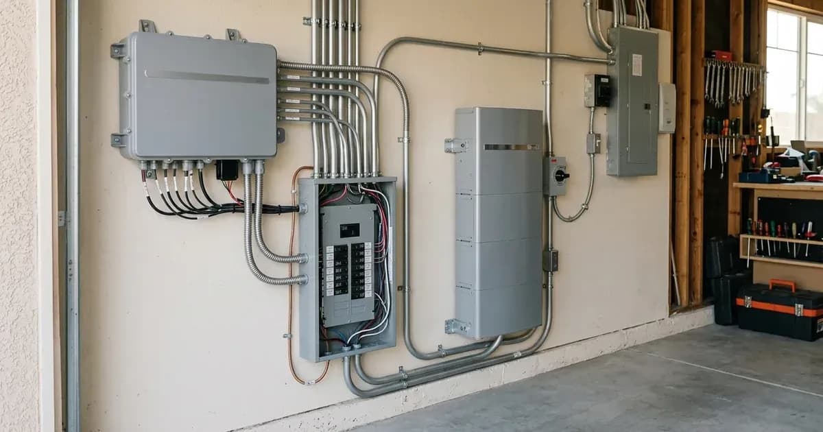
Microgrid interconnection wiring for an Enphase IQ System Controller 3 or 3G involves connecting solar photovoltaic (PV) systems, battery storage, and potentially a generator, to create a self-sufficient electrical network that can operate both connected to and isolated from the main grid. This setup allows for seamless transitions between on-grid and off-grid operation, providing energy resilience. The wiring ensures that all components communicate correctly and safely manage power flow within the household and with the grid.
How microgrid systems manage power flow and safety
A microgrid system, facilitated by a system controller like the Enphase IQ System Controller, is designed to manage complex power flows. It intelligently directs electricity from solar panels, batteries, or the grid to household loads. When the grid is available, the system can export excess solar energy or charge batteries. During a grid outage, the system automatically disconnects from the main grid and forms its own independent microgrid, drawing power from solar and batteries to maintain essential services.
The system is "Engineered for residential and commercial off-grid and grid-parallel energy storage systems worldwide." This capability relies on precise wiring and control to ensure safety and functionality. Critical safety measures include proper earthing and circuit isolation. For instance, you must "Bond inverter chassis ground and battery metal enclosure to the main installation earthing terminal." This ensures that in the event of an electrical fault, current is safely directed to the earth, preventing electric shock.
The system is also "Compatible with standard single-phase and three-phase electrical distribution systems globally," which means its wiring must integrate seamlessly with existing household electrical infrastructure while adhering to local standards.
Essential wiring practices for microgrid components
Wiring a microgrid system involves several critical steps, particularly concerning Current Transformers (CTs) and general electrical safety. CTs are vital for monitoring power flow and ensuring the system operates correctly.
Current Transformer (CT) Installation
Correct CT clamp installation is paramount for the system to accurately measure energy consumption and production. official documentation states: "Install Current Transformer clamps with arrows pointing towards the household loads away from the grid incomer." This ensures that the system correctly interprets the direction of energy flow.
An incorrect installation can lead to operational issues. "Negative power flow during high household consumption indicates inverted CT clamp installation." If you observe such readings, it suggests the CT clamps are installed backwards and need to be reoriented.
Safety Warning: "Ensure complete AC circuit isolation and lock-out before installing CT clamps on live busbars." Working on live electrical components is extremely dangerous and can result in severe injury or death. Always de-energise and lock out circuits before beginning any work.
Earthing and Bonding
Proper earthing (grounding) is a fundamental safety requirement for any electrical installation, especially those involving inverters and batteries. As noted, you must "Bond inverter chassis ground and battery metal enclosure to the main installation earthing terminal." This creates a safe path for fault currents, protecting both equipment and personnel.
General Wiring Compliance
All wiring must meet stringent regulatory and safety standards. The system "Complies with international microgeneration safety and grid protection standards." This compliance extends to the installation practices.
What you can check yourself, and what you cannot
While understanding the principles of microgrid wiring is beneficial, the actual installation and modification of such systems are complex and hazardous tasks that require professional expertise.
Task / Procedure | Homeowner Scope (Visual & Monitoring) | Qualified Electrical Professional Scope |
|---|---|---|
CT Clamp Orientation | Verify arrow points toward loads away from grid incomer | Isolate and lock out live busbars before CT clamp mounting |
Telemetry & Flow Readings | Check app for anomalies (e.g. negative flow under load) | Diagnose phase mismatch and re-terminate CT sensors |
System Bonding & Grounding | Visual check of external grounding conductors | Bond inverter chassis and battery enclosure to main earthing terminal |
Enclosure & Feeder Wiring | Inspect exterior casing without opening enclosures | Terminate DC conductors, AC feeders, and auxiliary cables |
Commissioning & Testing | Verify normal status LEDs and dashboard reports | Perform insulation resistance testing and polarity verification |
What you can check yourself:
- Visual inspection of CT clamp direction: You can visually confirm that the arrows on the CT clamps are pointing towards the household loads and away from the grid incomer. If you notice negative power flow readings during high consumption, this is a strong indicator of inverted CT clamps.
- System monitoring data: Reviewing your system's monitoring data can help identify anomalies like negative power flow, which might suggest an installation error.
What you cannot and should not do yourself:
- Any electrical wiring or connection: "All DC conductors, AC feeders, and auxiliary control cables must be installed in compliance with applicable national electrical codes and verified by an accredited electrical engineer." This includes connecting the IQ System Controller, PV arrays, batteries, or generators.
- Opening electrical enclosures: Opening the IQ System Controller or other main electrical enclosures should only be done by qualified personnel.
- Troubleshooting beyond visual checks: If you suspect a wiring issue, especially after observing negative power flow, contact an accredited installer or electrician. Do not attempt to re-wire or adjust components yourself.
- Commissioning: "Complete pre-commissioning checks, insulation resistance testing, and polarity verification prior to final energization and utility permission to operate." These are specialist tasks.
Attempting to perform electrical work without proper qualifications and safety training can lead to serious injury, damage to equipment, and may void warranties or insurance.
What the published sources do not tell you
The provided official documentation offers general compliance statements and high-level safety instructions rather than specific wiring diagrams or detailed technical specifications for the Enphase IQ System Controller 3 or 3G.
Specifically, the sources do not provide:
- Detailed wiring schematics: There are no specific diagrams illustrating how to connect the Enphase IQ System Controller 3 or 3G to PV arrays, batteries, generators, or the main electrical panel.
- Specific model numbers or ratings: published guidance does not include power ratings, voltage ranges, or current limits for the Enphase IQ System Controller 3 or 3G, nor for compatible batteries or PV systems.
- Generator integration specifics: Details on how to wire a generator for seamless integration with the Enphase IQ System Controller, including transfer switch requirements or control signals, are not present.
- Neutral-forming details: The specific mechanisms or wiring requirements for the IQ System Controller to form a neutral connection in an off-grid scenario are not described.
- Communication wiring specifics: While mentioning "shielded twisted-pair cabling and verify proper RS485 communication baud rate settings," published guidance does not detail which components use RS485, their specific pinouts, or required baud rates for the Enphase system.
- Site-specific sizing or architecture guidance: The document notes that system architecture and sizing are "according to site-specific engineering drawings, local utility connection capacity, and manufacturer equipment ratings," but does not provide these specific details.
For these critical details, you must consult the official Enphase installation manuals for the IQ System Controller 3 and 3G, as well as local electrical codes and the designs provided by your accredited installer.
Add a battery at a surveyed price
Installers quote supply and fitting of the battery on this page for your existing or new system.
How this pays for the site: installers pay SolarNevs a fixed introduction fee when we pass them a genuine enquiry. They cannot pay to appear higher, and our surveyed prices are published before any introduction. You can also take our dated price tables straight to any installer.
Frequently asked questions
What are the primary technical requirements for enphase iq system controller 3 and 3g microgrid wiring guide?
Key requirements include compliance with local grid codes, correct equipment certification, and proper electrical isolation.
Who is authorized to install and inspect enphase iq system controller 3 and 3g microgrid wiring guide?
All high-voltage DC, AC grid tie-in, and switchboard modifications must be performed by a qualified, accredited electrical professional.
How is export power limited in enphase iq system controller 3 and 3g microgrid wiring guide?
Export limiting is achieved using certified bidirectional smart meters or power sensors providing dynamic feedback to the inverter system.
References
- Enphase IQ System Controller 3/3G data sheet (PDF download) — accessed 15 September 2026
- Enphase Store - IQ System Controller 3G product page (connects grid, IQ Batteries, generator and PV microinverters; MID function) — accessed 15 September 2026
Related guides
More from what to buy — and how not to get cheated.